12 Multifunction Control Panel
®®
SECTION 2 - INSTALLATION
Mounting the Peripherals
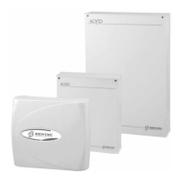
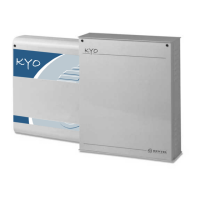
The Main Unit
Refer to the Main Unit Manual for the respective installation instructions.
Mounting Keypads
Work carefully through the following steps:
CAUTION - For CLASSIKA keypad, before removing the keypad cover, OPEN
THE FLIP [48] COMPLETELY.
1. Insert a sharp screwdriver into openings to release the hooks [58], then
remove the cover taking care to slide the terminal board [53] out delicately.
2. Pass the connection wires through the opening [57].
3b If it is to be flush mounted, use the holes [59b] to fix the base to the wall.
3b. If it is to be mounted on a model 503 box or similar, use the holes [59a] to fix
to the base.
To fix the keypad perfectly, use with the perforated sphere [65a] at the base.
4. Fix the anti-tamper plug [61].
5. Complete the connections between the terminal board [53] and Control
panel BPI Bus.
WARNING - DO NOT connect the Keypad to the bus when the bus is live; if
this is not possible connect the bus terminals in the following order: -, +, R, C.
6. Assign the Keypad Address (refer to ‘Addressing Devices’, further on in
this section)
.
7. Reattach the frontplate by first hooking it to the clips [65c], then by blocking
it by applying light pressure until the clips are released [58].
Mounting PROXI Proximity Readers
Work carefully through the following steps:
1. Remove the screws [47] and the frontplate.
2. Pull the wires through the cable entry [57].
3. Drill the holes [59a] for the backplate.
4. If necessary, install the Snatch Microswitch [56]. Ensure that the Snatch
Microswitch lever is held firmly in position (pressed down) by the plastic
tooth on the Snatch bracket [61]. Using a screw, secure the Snatch bracket
to the wall.
In order to comply with the standards outlined in Performance Level 11 of the CEI
79-2 certification, Readers must be fitted with Snatch Microswitches.
 Loading...