30 Multifunction Control Panel
®®
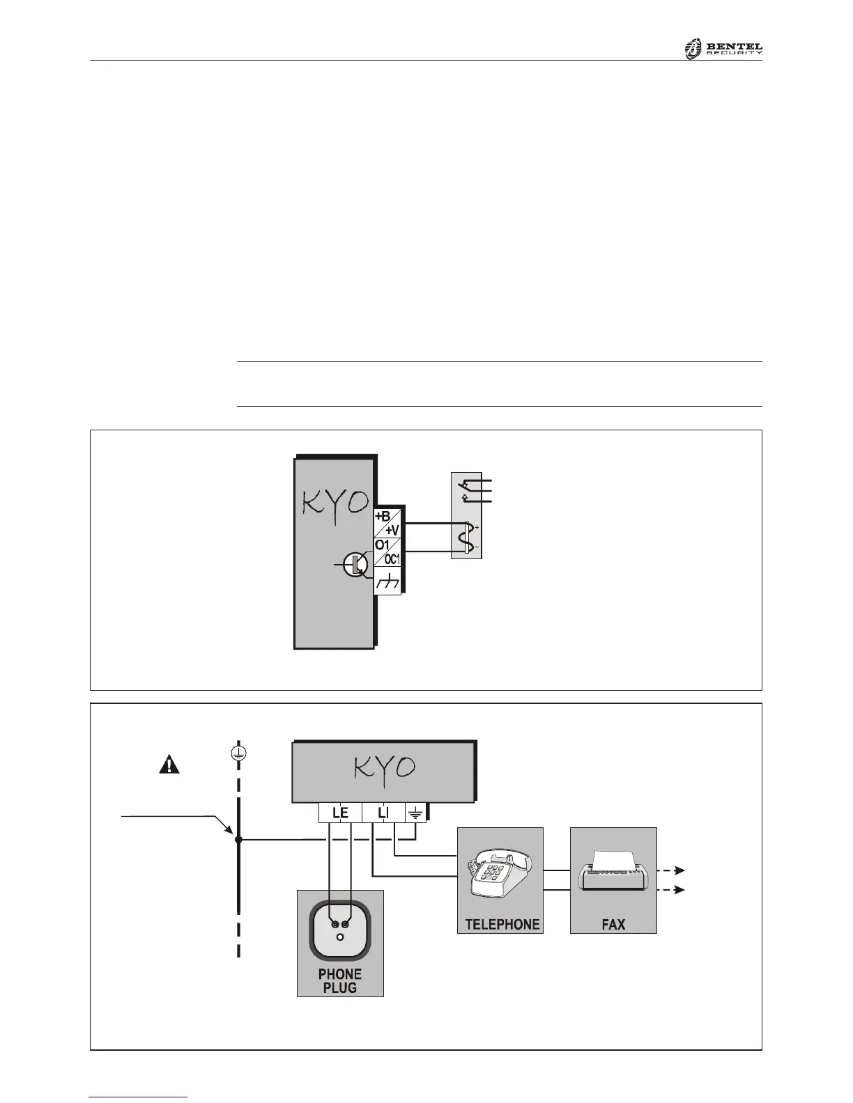
Figure 2.14 - Connecting the Telephone Line
Auxiliary Device (Open Collector)
KYO4, KYO8, KYO8W and KYO32 have 3 programmable Open-Collector
outputs (terminals 23 [O1], 24 [O2] and 25 [O3]). KYO8G, KYO8GW and
KYO32G have 5 programmable Open-Collector outputs (terminals 38[O1],
39[O2], 40[O3], 41[O4] and 42[O5]). Kyo16D have 2 programmable Open-
Collector outputs (terminals 22 [OC1] and 23 [OC2]). These terminals can be
set up as Normally Open (NO) or Normally Closed (NC), and can be activated
by one or more events (to be selected during the programming phase—refer to
the ‘PROGRAMMING FROM PC’ section for the list of events).
The wiring diagram in Figure 2.13 illustrates the operating principles of a NO
Open-Collector output (terminal [O1] on the Control panel) which will be acti-
vated by the ‘Exit Delay’ event.
The CEI 79-2 approval applies only when the Expander OC Outputs are inter-
faced with relays, installed inside the Expander box.
Mains
Earth
This connection
is necessary
Other
devices
Figure 2.13 - Connecting an OC Output
Relay
Contacts
Relè
 Loading...