28 Multifunction Control Panel
®®
Test Vibrat 018
DDIIZZZZ
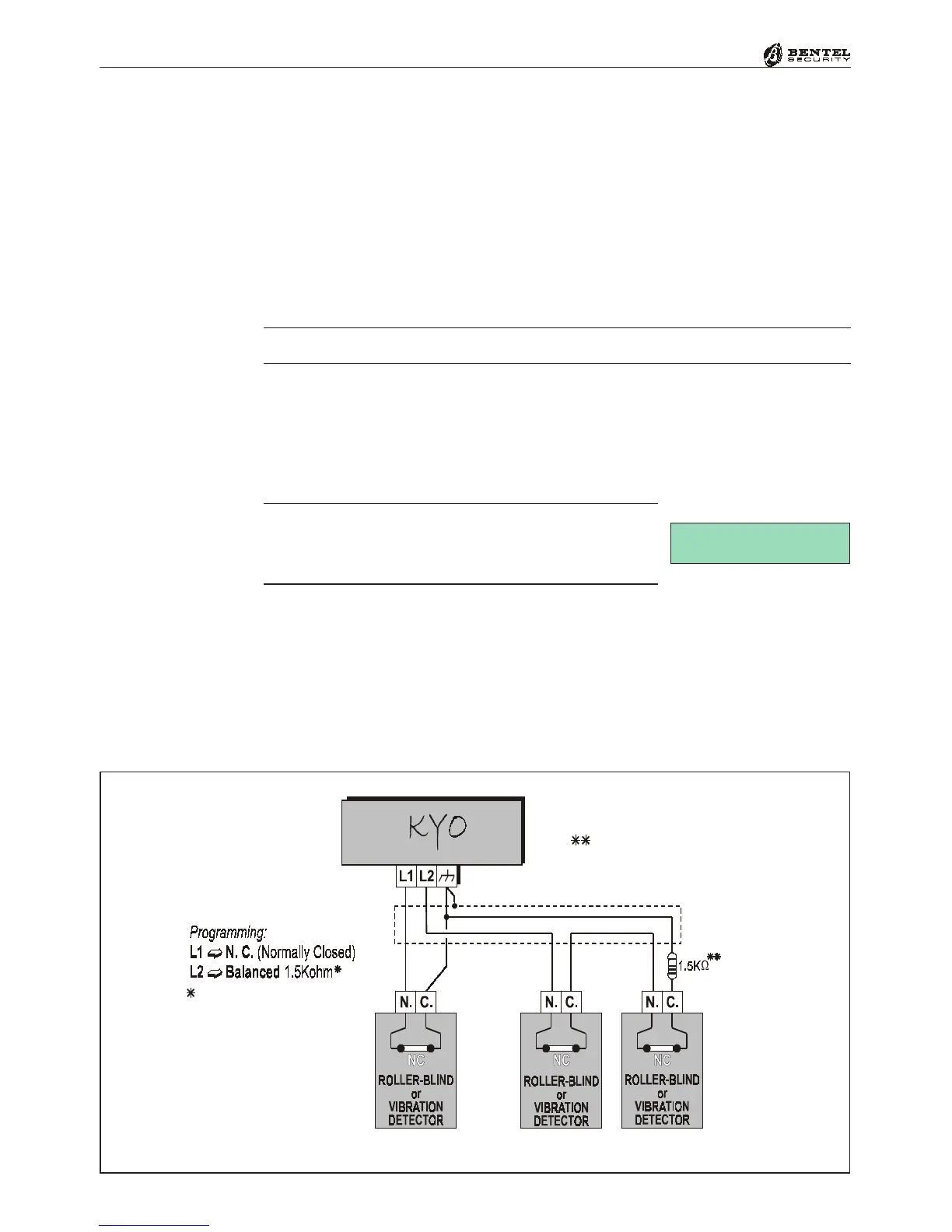
Figure 2.11 - Connecting Roller blind and Vibration detectors to a N.C. and a Balanced Line
Connecting Roller-Blind and Vibration Detectors
Zones 1 through 6 of the KYO8 and KYO32 Models, and all zones of the KYO4
(zones 1 through 2 for Kyo16D) support Roller-blind and Vibration detectors.
The zones must be programmed respectively with either the Vibration or
Roller-blind attribute (refer to the ‘PROGRAMMING FROM PC’ section in
this Manual), and can be set up as Normally Closed (N.C.) or Balanced 1.5 KΩ
(BAL). The wiring diagram in Figure 2.11 shows a typical connection. The 1.5.
KΩ (600ohm for Kyo16D) Balance Resistor must be connected to the last de-
vice, as shown in Figure 2.11.
The 1.5 K
ΩΩ
ΩΩ
Ω
Balance Resistors are not supplied.
If the system has an LCD Keypad, it will be possible to Test the sensitivity of the
‘Vibration’ zones. The system must be put in SERVICE MODE, by leaving a
Digital Key in a Reader, or by inserting the INHIBIT ALARMS Jumper [8] (the
zones must be tested SEPARATELY). The display will show the Test message
and the ‘Shock’ value (0 through 20).
IMPORTANT - For the most reliable results, the
‘Vibration’ attribute must be disabled on all zones
except the one being tested.
600 Ohm
on KYO16D model
Parallel of two 1.2 Kohm resistors
Balanced 600 ohm
on KYO16D model
 Loading...