27
®®
Section 2 - Installation
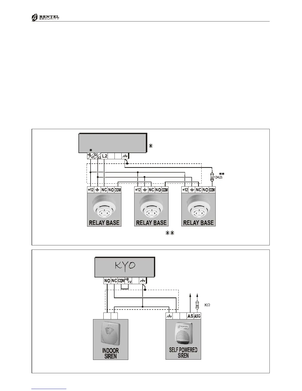
Alarm Siren
All types of signalling devices can be connected to the free-voltage relay (termi-
nals [NC], [NO] and [COM]). The wiring diagram in Figure 2.10 illustrates the
wiring of a Self-powered Siren (e.g. CALL) and an Indoor Siren (e.g. Wave). In
a connection of this type, the Self-powered Siren which will activate when the
Positive signal drops on terminal [+N].
Figure 2.10 - Connecting Indoor and Self-powered Sirens
+
+N
To
Tamper line
–
10
Figure 2.9 - Connecting Relay Bases to a Balanced Line
.<2
+B
+F
+V AUX
on KYO4-8-8W-32 models
on KYO8G-8GW-32G models
on KYO16D model
1,2K
on model KYO16D
 Loading...