13
®®
Section 2 - Installation
5. Using the cable [70], complete the connections to the Control panel BPI Bus.
6. Assign the Addresses to all the peripheral devices (refer to ‘Addressing
Devices’, further on in this section).
7. Reattach the frontplate.
PROXI Readers must be located at least 50 cm apart.
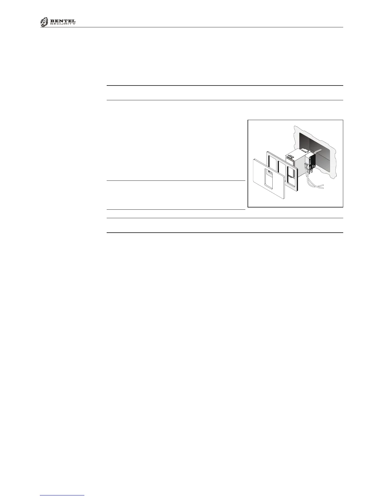
Mounting ECLIPSE2 Readers
ECLIPSE2 Key Readers can be flush mounted
on standard electricity outlet boxes.
Before mounting the Reader, complete the
connections between the ECLIPSE2 terminal
board [53] and Control panel BPI Bus.
In order to comply with the standards outlined in
Performance Level 11 of the CEI 79-2 certification,
Readers must be fitted with Snatch Microswitches.
ECLIPSE2 Readers must be located at least 50 cm apart.
Using the Address Microswitches [51], assign the Reader Address (refer to ‘Ad-
dressing Devices’, further on in this section). For security reasons, outdoor flush-
mounted Key Readers must be fitted with tamper protection (see Figure above).
M-IN/OUT Expanders
The Input and Output Expanders must be located as near as possible to the
peripherals they are connected to. The Input and Output Expanders boxes can
be surface or flush mounted.
To install the Expanders:
1. Remove the Wire entry knockout ([57] or [85], as required.
2. For Surface Mounting: drill the holes for the back box and Snatch
bracket (screw locations [84] and [61] respectively).
For Surface Mounting on Mod.503 boxes or similar: drill the holes for
the back box and Snatch bracket (screw locations [83] and [61] respectively).
The M-IN/OUT expander can if necessary also be housed in a container
other than the dedicated one. In this case, jumper [78] must be closed (in-
serted) to disable the Tamper contact [77] and the Anti-snatch contact [82].
3. Pull the wires through the wire entry.
4. Attach the back box and Snatch bracket.
5. Replace the Expander Module [80] (see Figure 1.3), ensure that it is held
firmly in place by the PCB clips [58] then, using the two screws [81], secure
it to the backplate.
6. Complete the connections on the terminal board [53].
To tamper line

 Loading...