26 Multifunction Control Panel
®®
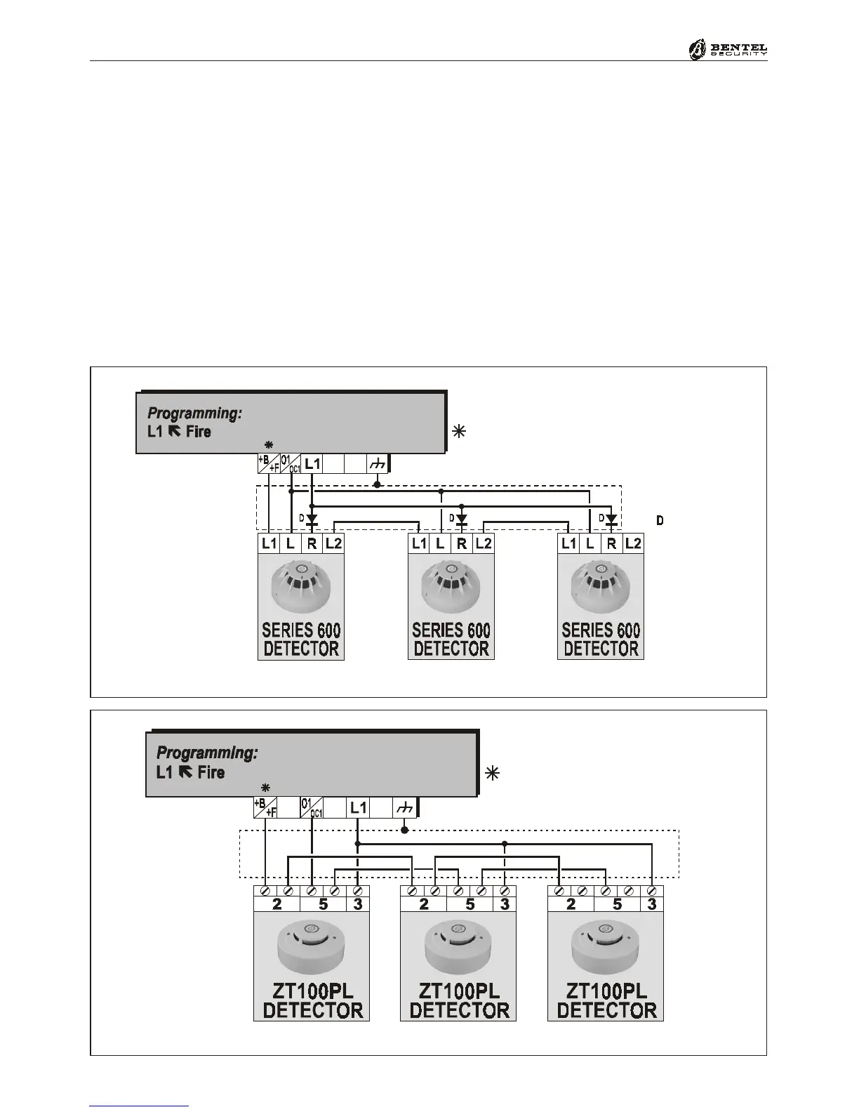
Figure 2.8a - Connecting series 600 detectors with Repeat Outputs
.<2
+B
+F
+V AUX
on KYO4-8-8W-32 models
on KYO8G-8GW-32G models
on KYO16D model
1N4148 diode
(or similar)
Connecting Fire Detectors (with Repeat Outputs)
This Control panel also accepts Fire detectors. The Alarm repeat outputs of the
Fire detectors must be connected to Fire zones (Normally Open -24 hour zone).
The wiring diagrams in Figures 2.8a and 2.8b shows three detectors, e.g.
Bentel’s 600 Series and Bentel’s ZT100PL Models (smoke) connected to
Alarm line [L1]. In a connection of this type, the Negative signal (Reset) is
supplied by the Normally Closed OC output (see [O1]).
The wiring diagram in Figure 2.9 shows a similar connection using a Relay Base.
In a connection of this type, the Control panel OC output (see [O2]) must be
programmed as Normally Closed, and the Alarm Line ([L2]) as Balanced 10K
(‘Balanced 1k2’ for Kyo16D Control Panels).
Connecting
Relay bases
Figure 2.8b - Connecting ZT100PL detectors (Smoke)
.<2
+B
+F
+V AUX
on KYO4-8-8W-32 models
on KYO8G-8GW-32G models
on KYO16D model
 Loading...