19
© Copyright by BIFFI Italia. All rights reserved.
“ICON2000”
instruction and operating manual
Section 618/1 chapt. C
Section 618/1
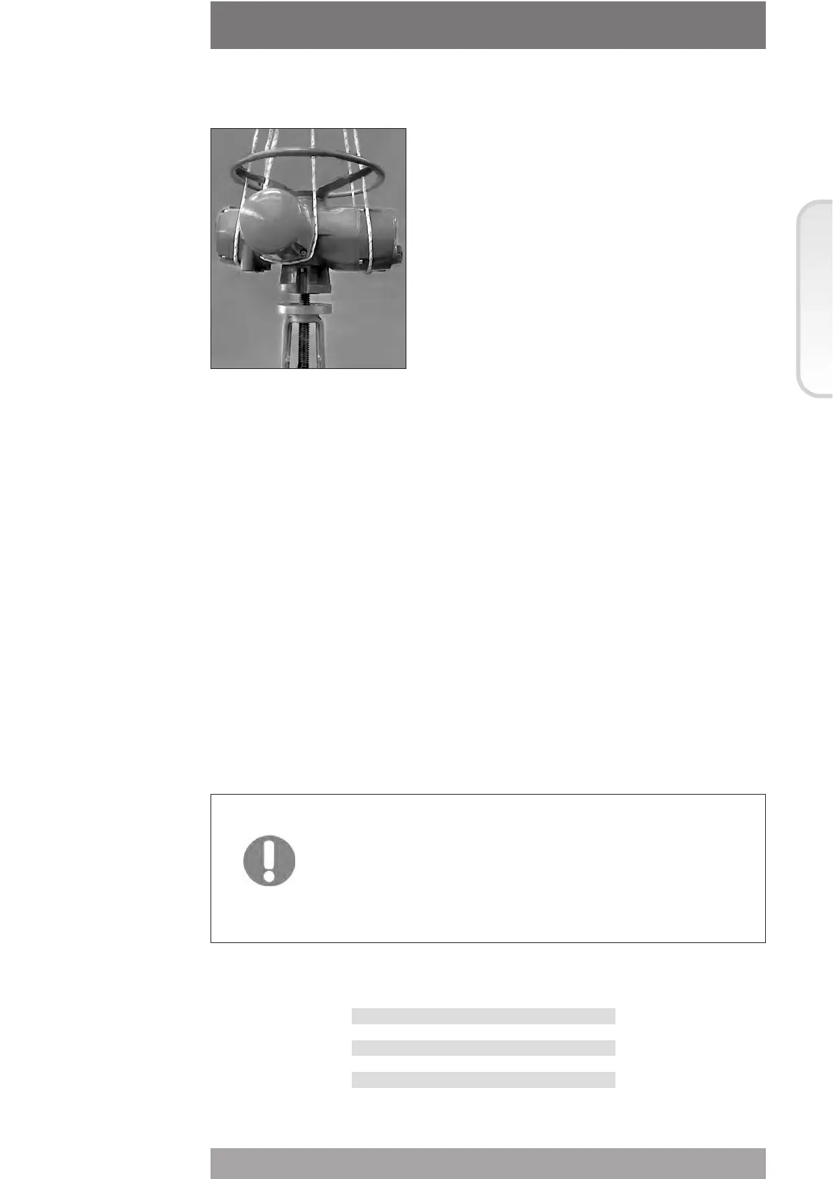
4.1 COUPLING TYPE “A”
Place the actuator vertically on the stem; screw the threaded bushing of the coupling block
on the valve stem, rotating (normally counter-clockwise) until the coupling block and flange
surfaces of the valve are securely in contact.
For safety purposes, rotate the handwheel in the opening direction for about two turns in
order to lift the valve gate from its seat to avoid (during bolt fixing) excessive axial thrusts on
the internal parts of the valve and of the actuator.
Depending on the conditions of assembly, it could be easier to separate the thrust block
from the actuator and mount it onto the valve yoke.
4.2 COUPLINGS TYPE “B1”, “B2”,”B3” AND “B4”
Check the dimensions of the valve mounting details, paying particular attention to the
protrusions of the valve stem in order to avoid any axial thrusts to the internal parts of the
actuator or the valve when the screws are tightened.
Engage the manual operation. Place the actuator vertically on the valve stem. Carry out the
coupling operations (if necessary with the help of manual operation); make sure no mating
parts are forced.
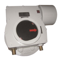
4.3 ACTUATOR FIXING
Important: In case the actuator is supplied without stud bolts and
nuts the following materials must be used as a
minimum:
- ISO class 8.8 for studs bolts and nuts
or
• ASTM A 320 Grade L7 (or L7M) for studs bolts
• ASTM A 194 Grade 4 for nuts
Model Tightening torque
010 40 Nm
020 150 Nm
030 150 Nm
040 300 Nm
050 150 Nm