© Copyright by BIFFI Italia. All rights reserved.
20
“ICON2000”
instruction and operating manual
5. Electrical connections
Before powering to the actuator check that the supply voltage details on the nameplate are
correct for the plant. Access to terminals for electrical connections and commissioning is
through the terminal cover, since all settings are non-intrusive. The removal of any other
covers without Biffi's approval will invalidate the warranty.
Biffi will not accept any responsibility for any damage or deterioration that may be caused.
Important: All the accessories (in particular cable glands) must be
certified.
As of 30 June 2003, the above accessories must carry the CE
certification conforming with 94/9/CE Directive.
5.1 PLANTS REQUIREMENTS
Protection devices (overcurrent breakers, magneto-thermal switches or fuses) should be
provided on the plant at Customer care, to protect the mains line in case of motor
overcurrent or loss of insulation between phases and earth.
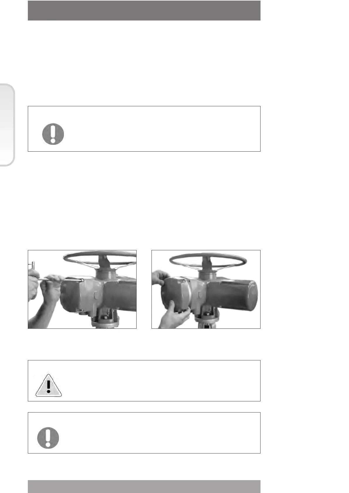
6. Removing the terminal board enclosure
Using a 8mm Allen key, loosen the four screws and remove the cover.
Warning: Do not damage the mating surface of the cover.
Important: In case the screws of the cover must be replaced, a SS AISI 316
must be used with minimum yield strength of 450N/mm
2
Section 618/1
Section 618/1 chapt. C