“ICON 2000v4"
instruction and operating manual
© Copyright by BIFFI Italia. All right reserved. Section 618/42 Page 4
Contents may change without notice
6. RS485 transmission mode
The ICON2000v4_DPV1 module uses a half duplex, multidrop, serial communication line RS485.
The module communicates with the Masters via its RS485 interface and the transmission media
consists in a shielded twisted pair cable. Transmission speed from 9.6kbit/sec to 1.5Mbit/sec are
available. One unique transmission speed is allowed for all devices on the bus when the system
works.
All devices are connected in a bus structure. Up to 32 station (Master and Slaves) can be connected
in one segment without repeaters. Repeaters can be used to extend the number of device up to 126
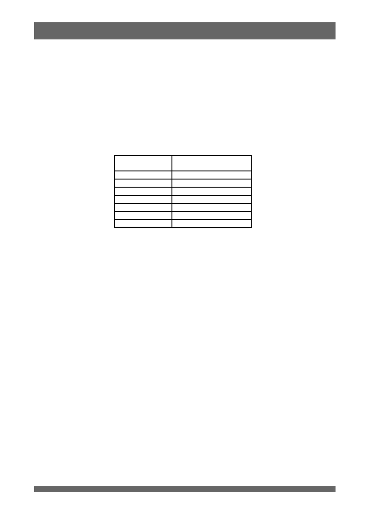
and to enlarge the network area. The following table shows the relationship between baud rate and
segment length.
Max. segment length
(no repeater)
The bus must be terminated by an active bus terminator at the beginning and at the end of each
segment. Only two terminations in one bus segment must be provided. To ensure error-free
operation, both bus terminators must be powered. The maximum cable length depends on the
transmission speed. Cable lengths indicated in table 2 are based on type A cable, as specified by the
EN 50170, having the following characteristics.
Impedance from 135 to 165 ohm
Capacity < 30 pF/m
Loop resistance 110 ohm/km
Wire gauge 0.64 mm
Conductor area > 0.34 mm
2
The use of cable of previously used type B is not recommended.
The data lines must not be reversed. Use of shielded cable is mandatory for having high system
immunity against electromagnetic disturbs. The shield should be connected to ground on both sides.
The data lines should be kept separate from all other cables. It should be laid in separate, conductive
and earthed cable trunking. It must be ensured that there are not voltage difference between
individual nodes of PROFIBUS DP.