“ICON 2000v4"
instruction and operating manual
© Copyright by BIFFI Italia. All right reserved. Section 618/42 Page 5
Contents may change without notice
The ICON2000v4_DPV1 module takes its electrical supply from the actuator power supply
module. The RS485 bus transceiver is isolated from the actuator electronics. Also the voltage
supply of the bus termination is isolated. The ICON2000v4_DPV1 module is equipped with on-
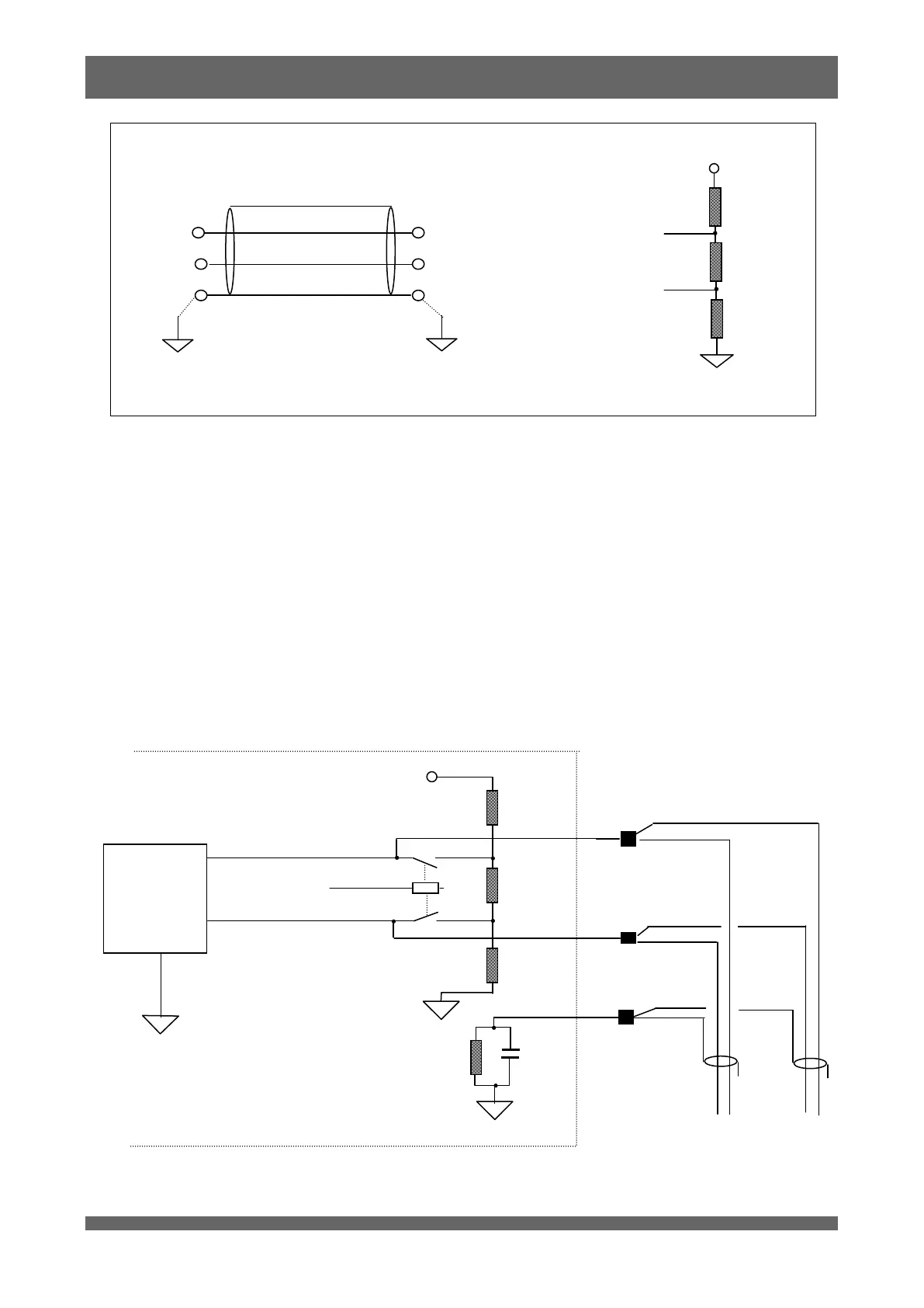
board bus termination that should be used when the actuator is at the beginning or at the end of the
bus segment and if there is no external termination. The bus termination can be switched on the data
lines by means of a link, configurable via local operator interface.
Since the bus termination is a crucial component to ensure error-free operation, it is important that
termination remains powered also when the actuator supply has left. If the internal termination are
used, it is suggested to connect to the actuator also an auxiliary 18/36 Vac/dc generated by safe
source that will supply just the actuator electronics and the PROFIBUS termination.
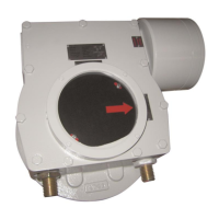
The figure below shows the wiring in case of not redundant connection. The termination must be
linked to the data lines only if the actuator is at the beginning or at the end of the bus segment.
PROFIBUS
RS485
transceiver