22
© Copyright by BIFFI Italia. All rights reserved.
“ICON2000”
instruction and operating manual
8. Terminal board
Important: The removal of any other covers without Biffi's approval will
invalidate the warranty. Biffi will not accept any responsibility
for any damage or deterioration that may occur as a result of
cover removal.
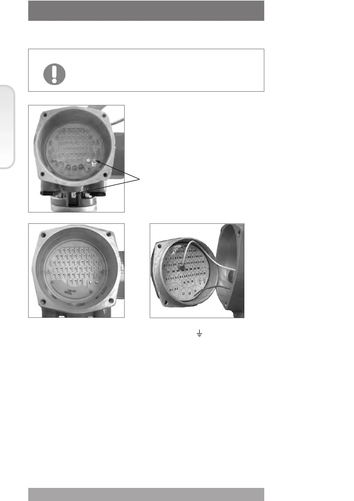
Terminate the ground connections to the ground stud marked . One internal and one
external ground studs are provided.
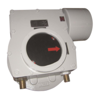
Check the wiring diagram (always enclosed with the actuator) and the layout displayed on
the back of the terminals enclosure cover, to ensure a correct electrical connection. All
terminations should be made by insulated ring or spade connectors using the appropriate
crimping tool. This operation will ensure easy and correct electrical connection.
Connect the motor supply cable previously sized in accordance with:
- the absorbed current correspondent to the actuator nominal torque with the torque limiting
device set at 100 percent (see the test certificate attached to the actuator)
- the applicable plant and safety norms.
Assemble the power terminals protective barrier, located in the terminal board
compartment, using the enclosed screws.
The control circuit (controls and signals) must be connected by means of a multicore cable
to the corresponding numbered terminals according to the wiring diagram.
The internal cables of the actuator are also numbered according to the wiring diagram.
Actuators are always delivered with the motors wound and connected in accordance to
customer requests. Voltage and frequency values are stated on the motor name-plate.
Section 618/1 chapt. C
Section 618/1
Ground studs