34
© Copyright by BIFFI Italia. All rights reserved.
“ICON2000”
instruction and operating manual
Section 618/2 chapt. E
Section 618/2
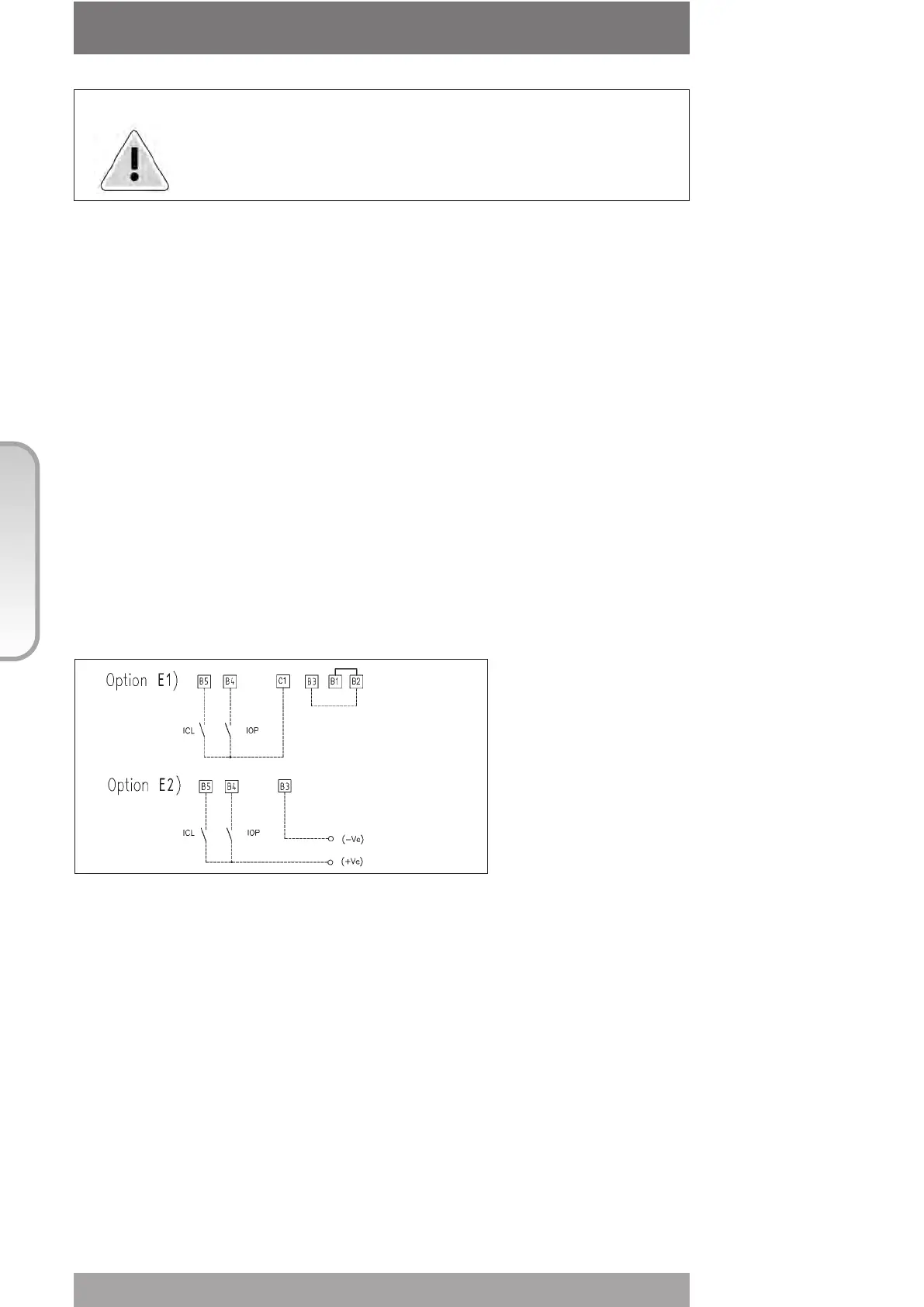
6.4 INTERLOCK INPUTS
Two additional inputs are available to inhibit actuator movement in open or close direction.
The controls are momentary, and the inhibit action continues until the relevant signal is
present. The interlock controls work when the Local Selector is in either LOCAL or REMOTE
positions. The ESD control overrides the interlock controls. The "VIEW and SET-UP"
features can configure the polarity of INTERLOCK signal as described in chap. I, paragraph
“INTERLOCK controls”.
The interlock inputs are opto-coupled and can be supplied by the internally generated
24VDC or by an external 20-125VDC or 20-120VAC (50/60Hz).
The signal levels are the following:
• Minimum ON signal > 20 VDC or 20 VAC (50/60Hz)
• Maximum ON signal < 125 VDC or 120 VAC (50/60Hz)
• Maximum OFF signal < 3
• Total current drawn from remote controls < 20mA
Warning: If customers wish the motor thermostat to be by-passed
during ESD operation any certification for actuator enclosure
in hazardous area would be invalidated.
The ESD command is opto-coupled. The circuits associated to the input can be supplied by
the internally generated 24VDC or by an external 20-125VDC or 20-120VAC (50/60Hz).
The signal levels are the following:
• Minimum ON signal > 20 VDC or 20 VAC (50/60Hz)
• Maximum ON signal < 125 VDC or 120 VAC (50/60Hz)
• Maximum OFF signal < 3V
• Current drawn from ESD controls < 15mA