37
© Copyright by BIFFI Italia. All rights reserved.
“ICON2000”
instruction and operating manual
Section 618/2 chapt. E
Section 618/2
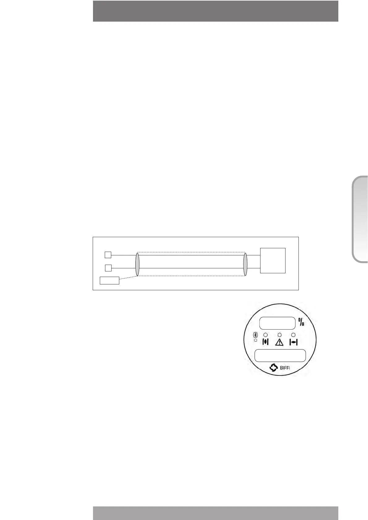
The figure below shows the wiring diagram:
The "VIEW and SET-UP" features can
configure different options which are
described in chap. I, paragraph “POSITIONER”.
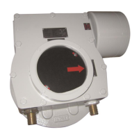
If the POSITIONER function is active the
alpha-numeric display indicates the value
of the position request in % (R%: xxx.x).
If the actuator is not provided with a lithium battery (or not supplied by the auxiliary
24VDC) and if the main voltage fails, the output 4-20mA maintains the last value. If the
actuator is moved by handwheel, the output 4-20mA will not be updated.
4-20mA analogue input
The 4-20mA analogue input is the position request R% signal and is used by the ICON2000
to position the valve in inching and modulating actuators. The “POSITIONER” routine
processes the input signal, compares the present actuator position % with the position
request R% and if the difference is greater than the dead band, the actuator is driven to
reach the requested position. 4mA corresponds to request R% = 0% = valve closed and
20mA corresponds to request R%= 100% = valve open. The relationship between position
and request signals can be reversed by the “Polarity” function. The 4-20mA input is
opto-coupled. The input impedance is less than 250 ohm. The loss of the 4-20mA input
signal is indicated as follows:
• Change-over of the monitor relay
• Alarm LED on
• List of ALARMS (see Section 3 chap.N, “Diagnostic messages”)
• Alarm log
37,5
NORMAL REMOTE
R:47% next?
Actuator terminals
cable
0Vdc
0V
4-20mA
B9
B8
GROUND
shield
4-20
mA
generator