18 | Chapter 2: Installation
BioTek Instruments, Inc.
Power-Up and System Test
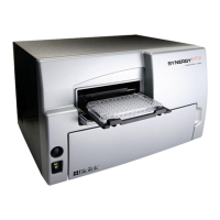
After you have installed the ELx800™ and connected the power supply, turn on
the instrument to run a system test. The on/off switch is located on the lower right
side of the base.
The
System Test begins with a check of the stepper motors and the analog power
supplies, to ensure that they have a proper input voltage level. The data flash
checksum, motor axis, and analog offset are then verified. The photodetector’s
dark current, noise, and gain are checked to ensure they fall within specific
pass/fail criteria.
If an error is detected, the reader will “chirp” and display an error code. See
Chapter 6 for a list of error codes. If no errors are detected, the reader will briefly
display SYSTEM TEST PASS.
The power-up system test does not produce a printed results report. To run the
test manually and obtain a printout of the system test values, start at the Main
Menu and press UTIL TESTS SYSTEM. See
System Test and Checksum
Test
in Chapter 4, or Connecting a Printer to the ELx800 on page 20 for more
information.
ELx800 Main Menu
Following successful power-up of the ELx800, the Main Menu appears:
R E A D Y 01:22PM 01/23 / 0 4
R E A D D EFIN
REPORT U T I L
• The Main Menu permits access to all onboard functions. See Main Menu in
Chapter 3 for more information, including a diagram showing the flow of
functionality (
Figure 15).
• The ELx800 front panel contains four circular buttons, referred to in this
manual as
“SOFT KEYS.” One SOFT KEY is positioned directly below
each selectable option in the display. To select a menu option, simply press
its corresponding
SOFT KEY. See ELx800 Front Panel in Chapter 3 for
additional instructions.
 Loading...