3: Install the MicroFlo’s Components | 15
MicroFlo Select Operator's Manual
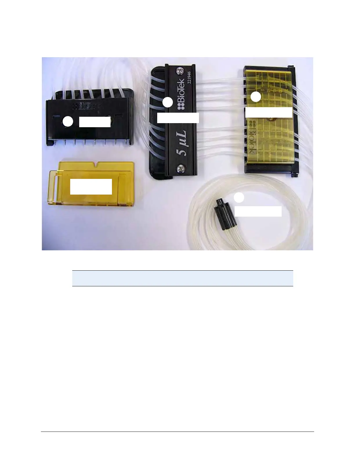
Tubing Cassette Diagram
Figure 4: Cassette Diagram
Important: remove the tip guard from the Tip Holder before installing
the dispense cassette.
1. Tip Holder: The cassette’s easiest part to identify, the tip holder fits into the
dispense arm to the right of the pump for positioning above the plate. The 1536
Cassette’s cover plate is made of steel, instead of Ultem® (polyetherimide) like
the other cassette types. Remove the temporary Tip Guard before installation.
2. Center Holder: The center holder is labeled to identify the size of the cassette
tubing. It also has a serial number for tracking purposes. It fits in between the
tip holder and the tube tensioner and fixes the tubes in place. On the MicroFlo
it slides into grooves on the right side of the pump.
3. Tube Tensioner: The transparent 5-mm scale on its front surface identifies the
tube tensioner. It has 8 internal screws for stretching the tubing, one for each
tube. The tube tensioner’s scale is useful when calibrating the cassette.
0.
4. Tube Organizer: At the opposite end of the cassette from the tip holder, the
tube organizer holds the 8 tubes together for inserting into the fluid vessel.
1
2
3
4
Tip Guard
(for shipping)
Ti
Holder
Center Holder
ube Tensioner
ube Or
anizer