38–
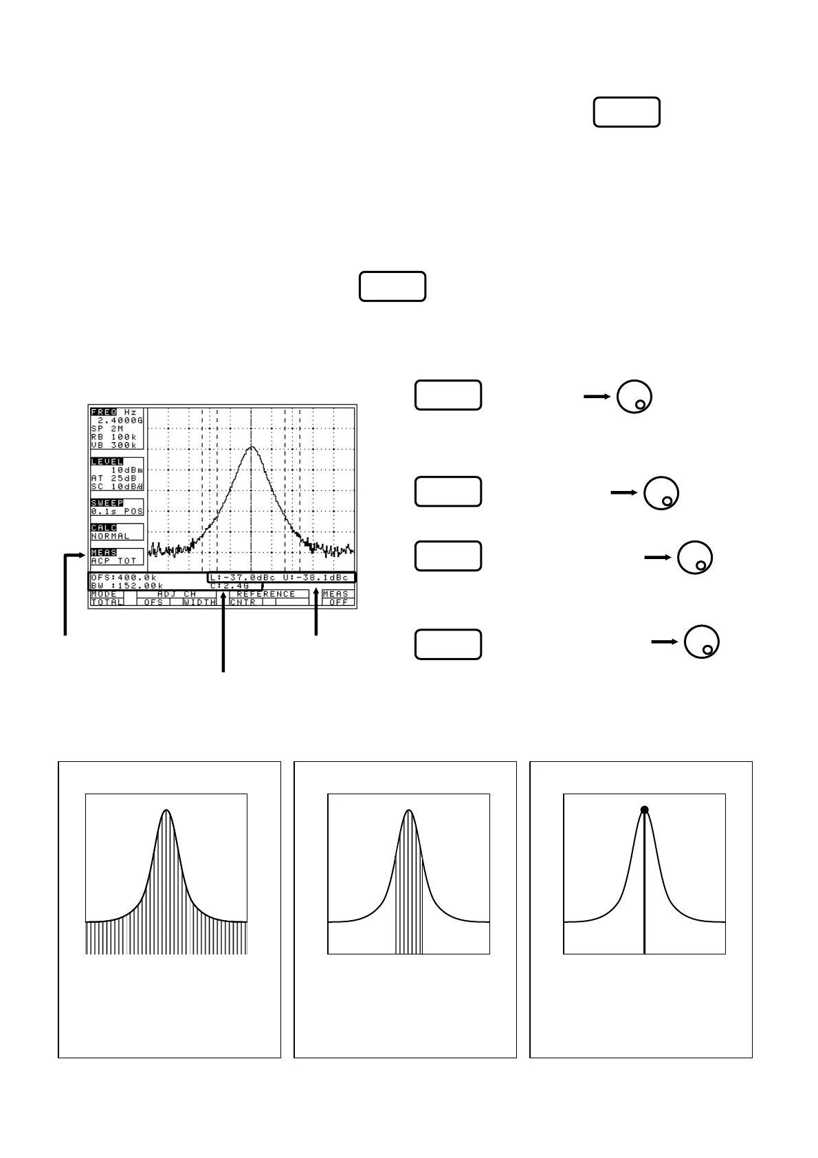
19.2 Adjacent channel leakage power measurement <Adj Ch Pw>
Measures the adjacent channel leakage power as the ratio of the power in the range specified by the offset
frequency against the reference frequency (reference carrier frequency) and the bandwidth, to the carrier
wave power. Two channels of adjacent waves on the upper and lower sides of the same offset frequency are
measured. In addition, you can select from three modes, TOTAL (total power method), REF BAND (in-band
method) and PEAK (reference level method), according to the classification of definitions of carrier wave.
· Mode selection and measurement
[Use (MODE) to select a mode: TOTAL, BAND or
PEAK.]
* It is each shown on MEAS area of LCD as “ACP TOT”, “ACP BAND” or “ACP PK”.
* The measured value and setting parameter are displayed at the right lower corner on the screen.
· Definition of the reference carrier for each mode
1. Use (Adj Ch OFS) to set the
offset frequency of adjacent channel.
* The offset is from the center of the reference carrier wave.
2. Use (Adj Ch WIDTH) to set the
band width of adjacent channel.
3. Use (REFERENCE CNTR) to set
the center frequency of reference carrier.
* [F4] is only for the TOTAL and BAND mode.
4. Use (REFERENCE WIDTH) to set
the band width of reference carrier.
* [F5] is only for the BAND mode.
F1
F2
F3
F4
F5
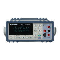
TOTAL (total power method)
This is based on the sum total of the
power of whole range on the screen.
Use [F4] to set center frequency of
the reference carrier wave.
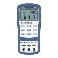
BAND (in-band method)
This is based on the sum total of the
power within the set bandwidth. Use
[F4] to set center frequency of the
reference carrier wave.
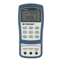
PEAK (reference level method)
This is based on the power of the pe-
ak on the screen. Center frequency of
the reference carrier wave is set up to
the peak inside the screen automati-
cally.
[Measured value]
[Adjacent channel
Leakage power
Measurement mode]
[Parameter]
F2