41–
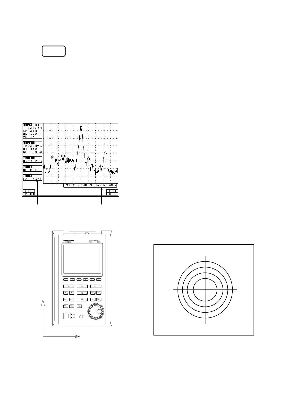
· Mode selection and measurement
Use (ANT) to select an antenna, AN301, AN302, AN303, AN304, AN305, AN306 or USER.
As soon as the antenna is entered, the measurement is taken.
* It is each shown on MEAS area of LCD as “E/F AN301”, “E/F AN302”, “E/F AN303”, “E/F AN304”,
“E/F AN305”, “E/F AN306” or “E/F USER”.
* “USER” is an original compensation table the user crates.
* Trace may exceed from a screen by antenna gain compensation.
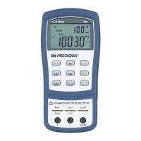
· Antenna directivity (reference data)
* All the data are those when the antenna is connected to the RF input with no obstacles around.
* However, data of AN305 is reference data of the conditions in which people have 2650/2652/2658
attached AN305.
So, the directivity changes in practice, because, for example, the unit is carried by people.
Unit of amplitude axis changes to [dBµV/m]
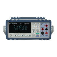
* Optimum center frequency and frequency span are
set according to the antenna.
In addition, a trace is not displayed for
frequencies outside those supported by the
antenna.
Example) case of AN301
Center frequency: 900MHz
Frequency span: 200MHz
F1
0°
90° 270°
180°
[Electric field strength [Measured value]
measurement mode]
E plane: X-Y axis (X direction=0°)
Y
X
(Refer to “25.3 Command description” for details.)