CHAPTER 3: INSTALLATION
29
components beginning at the bottom of the rack, then work to the top. Do not exceed your rack load
rating.
CAUTION: Power Considerations -
Connect only to the power source specified on the unit. When multiple electrical components are installed
in a rack, ensure that the total component power ratings do not exceed circuit capabilities. Overloaded
power sources and extension cords present fire and shock hazards.
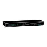
To install the rack mounting bracket:
1. Remove the two rack mounting screws from each side of the Octet switch.
2. Place the rack mounting brackets next to the switch as illustrated in Figure 3-4.
3. Insert the screws supplied with the rack mounting kit through the holes of the brack-
ets and into the Octet switch. Tighten the screws securely.
Install the Octet switch into the rack using the approved method of the rack manufacturer.
Figure 3-4. Octet Switch Rack Mounting Diagram
3.4 Installing an Octet Switch
To install a new Octet switch, you will connect power sources, configure network settings
and connect the switch to the local area network (LAN).
NOTE:
Turn off the Octet switch and disconnect the power cord from the AC outlet before servicing.
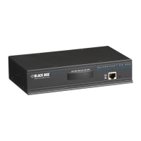
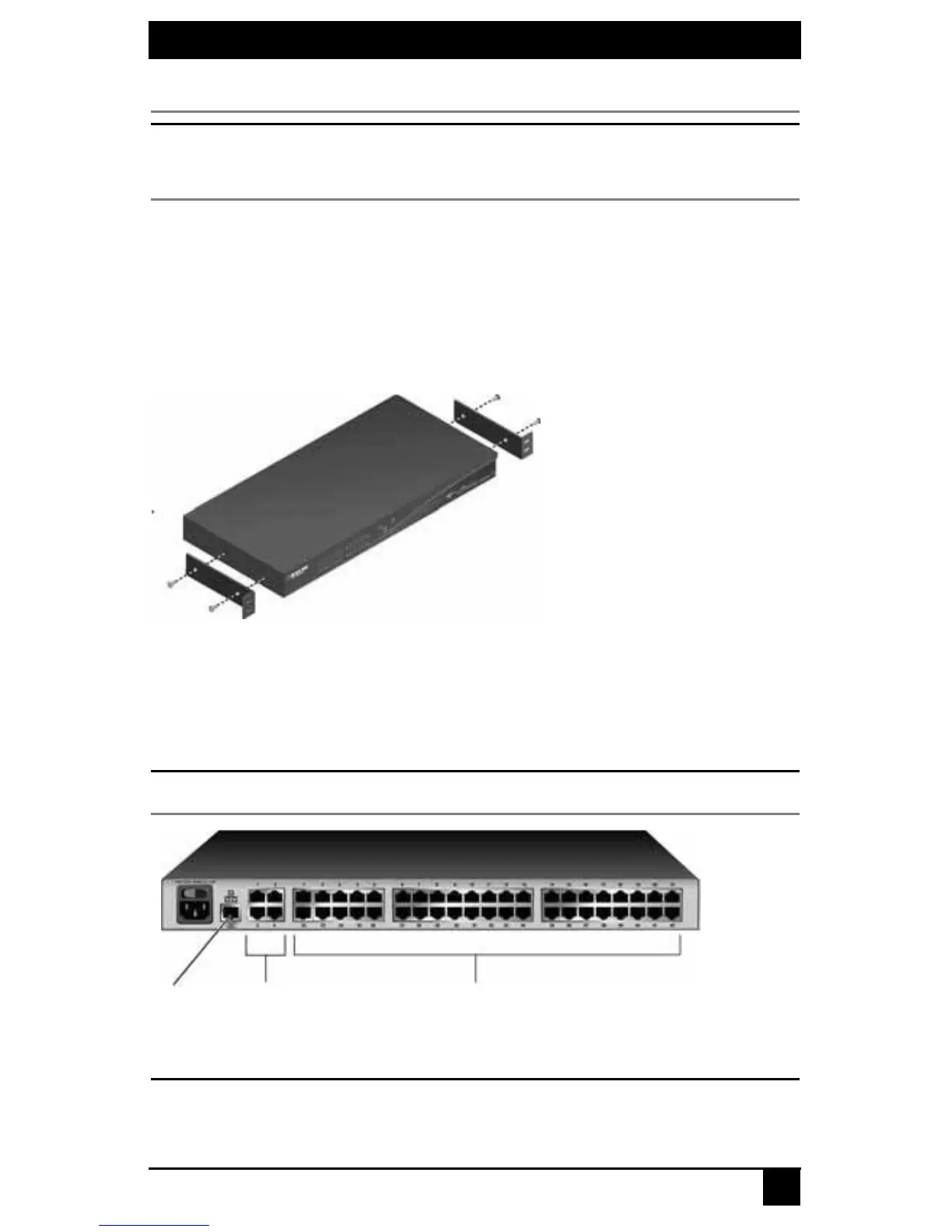
Figure 3-5. Example of an Octet Switch Back Panel (KV1700A/E Switch Shown)
CAUTION:
To reduce the risk of electric shock or damage to your equipment -
- Do not disable the power cord grounding plug. The grounding plug is an important safety feature.
- Plug the power cord into a grounded (earthed) outlet that is easily accessible at all times.
Network
Port
User
Ports
Server Ports