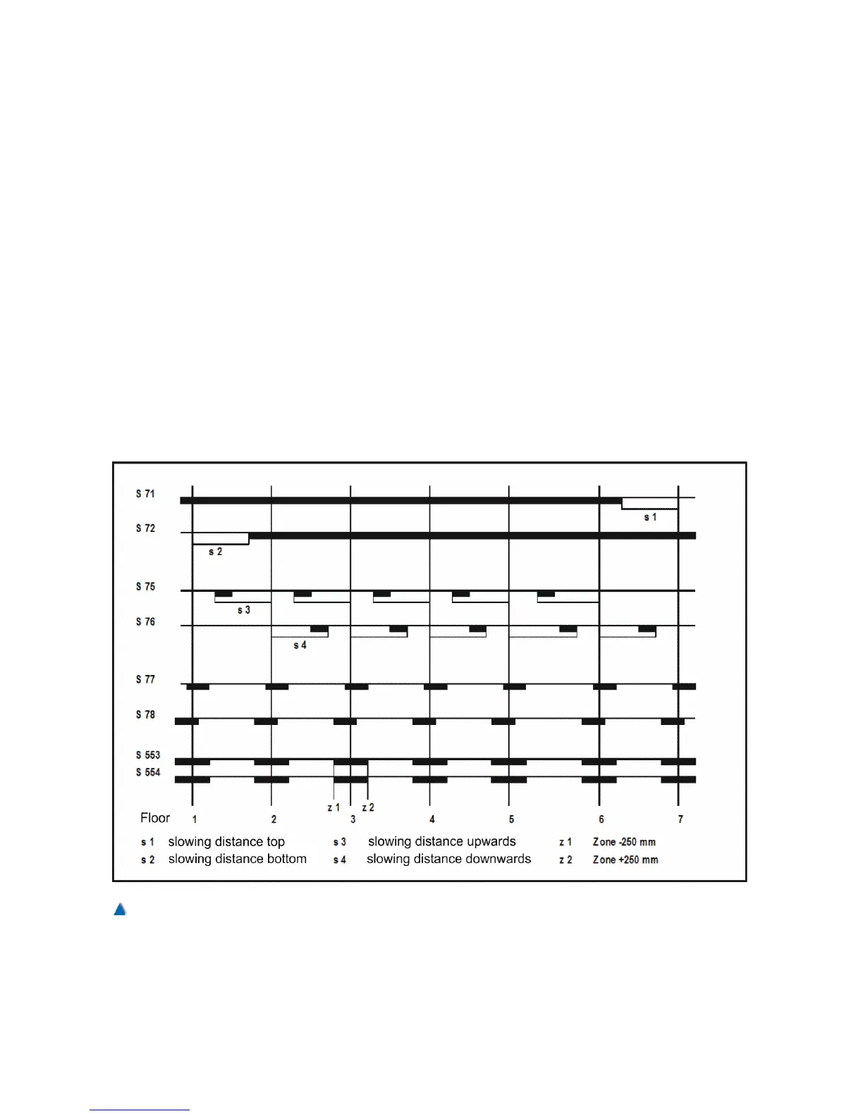
6.7 Assembly of the Magnet Switches
If magnet switches are to be used, they are to be mounted on the car
in a way that they pass by the magnets at a distance of approx. 5 mm
while the car is travelling through the shaft.
Definition of the Switches:
S71 Correction switch top Normally closed
S72 Correction switch bottom Normally closed
S73 Re-levelling switch up Normally open
S74 Re-levelling switch down Normally open
S75 Impulse up Normally open
S76 Impulse down Normally open
S77 Level position switch up Normally open
S78 Level position switch down Normally open
S553 Zone switch "A" Normally open
S554 Zone switch "B" Normally open
50 Installation Manual System »bp308« – Installation and Commissioning