Preferably, these additional speeds are to be used for
inspection and emergency operations.
ZE3 Additional speed V_ZE3
This input may activate different functions of the inverter, to
be preset in the menu INTERFACES. The additional speed
V_ZE3 was selected a factory.
BCT Brake chopper temperature. At this input, you can monitor
the temperature switch or the malfunction output of the brake
chopper.
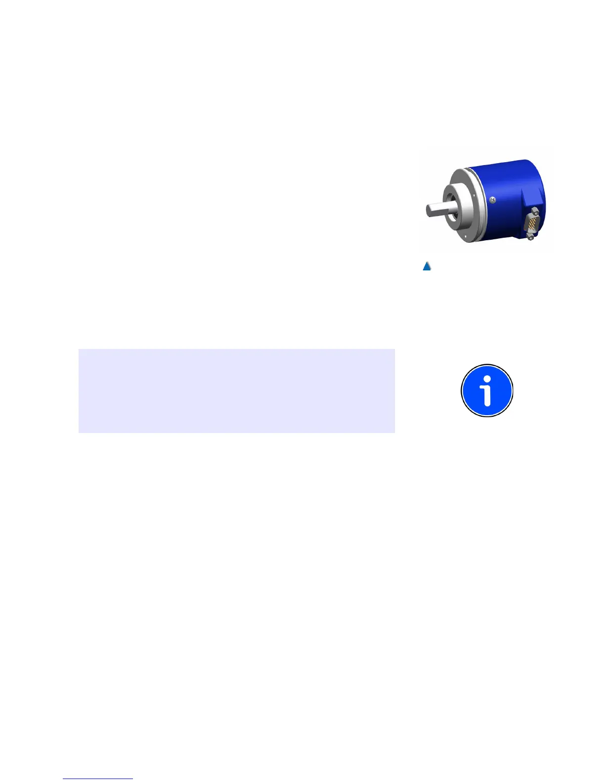
7.11 Installation of the Absolute Encoder
The absolute encoder is equipped with a 9-pin D-sub plug, the
assignment of which conforms with the CANopen standard. The CAN
Bus is terminated in the AWG-05 CANopen (type GXP5W.Z06 ).
If the absolute encoder has been mounted on the car, its connect-
ing cable can be plugged directly into the socket on the CLK.
If the absolute encoder is installed in the shaft head, its connecting
cable can be plugged into the respective socket in the control
cabinet.
INFO
Some types of position systems always terminate the can bus. If the
position system is mounted and connected on the car, termination via
the DIP switch 2 has to be deactivated on the CLK-03. You can find
information on terminating devices in their accompanying manuals or
online at www.CANopen-Lift.org
7.12 Interconnection of the Group
By means of the interconnection of the group, the lift control units
communicate with each other and transmit the well signals.
The connection »CAN2« serves as an interface for the interconnec-
tion of the group. The data lines must be twisted. They lead from the
terminals of the BPC to the terminal strip of the lift control unit. Con-
nection to the other members of the group is given by a plug con-
nector
The lines of the well signals are connected to the group as
described in the »Topology« section. If the shaft signals have been
connected to the control units in a conventional manner, they are
translated into CANopen data by components such as.
73