8.11.3 Read-in Travel with Absolute Encoder
After completing all these settings, you can initiate the read-in travel
in compliance with the following instructions. During the read-in
travel, the flush-level positions of every landing are precisely determ-
ined and memorised in the program memory. From the data gathered
by the read-in travel combined with the parameters set, the control
program calculates the virtual floor selector.
INFO!
It is recommended that two persons carry out the read-in travel
together. It is of utmost importance that the flush-level positions are
approached and read-in with perfect precision as the control system
calculates the landing parameters from the values read in.
Please proceed as follows:
1. Switch the lift to the INSPECTION operation mode.
2. Activate the ABSOLUTE ENCODING menu and then READ-IN
TRAVEL (It is possible to leave the program by pressing the
Call/End button at any time).
3. Move the lift to the bottom landing (landing 1) as near as possible
to the flush-level position with the inspection button. For a rope
traction lift, you reach this precise position by releasing the brakes
and turning the hand wheel.
4. For a hydraulically operated lift, approach the precise flush-level
position of the bottom landing by operating the emergency valve
or the hand pump.
5. After positioning the lift flush with landing level 1, activate either
the OK button of the LC display or the cabin call button of landing
1. Button 1 lights up to acknowledge the correct reading-in of the
flush-level position.
6. Repeat this procedure for every other landing as well.
7. After reading in every flush-landing level position, you can switch
the lift back to normal operation mode.
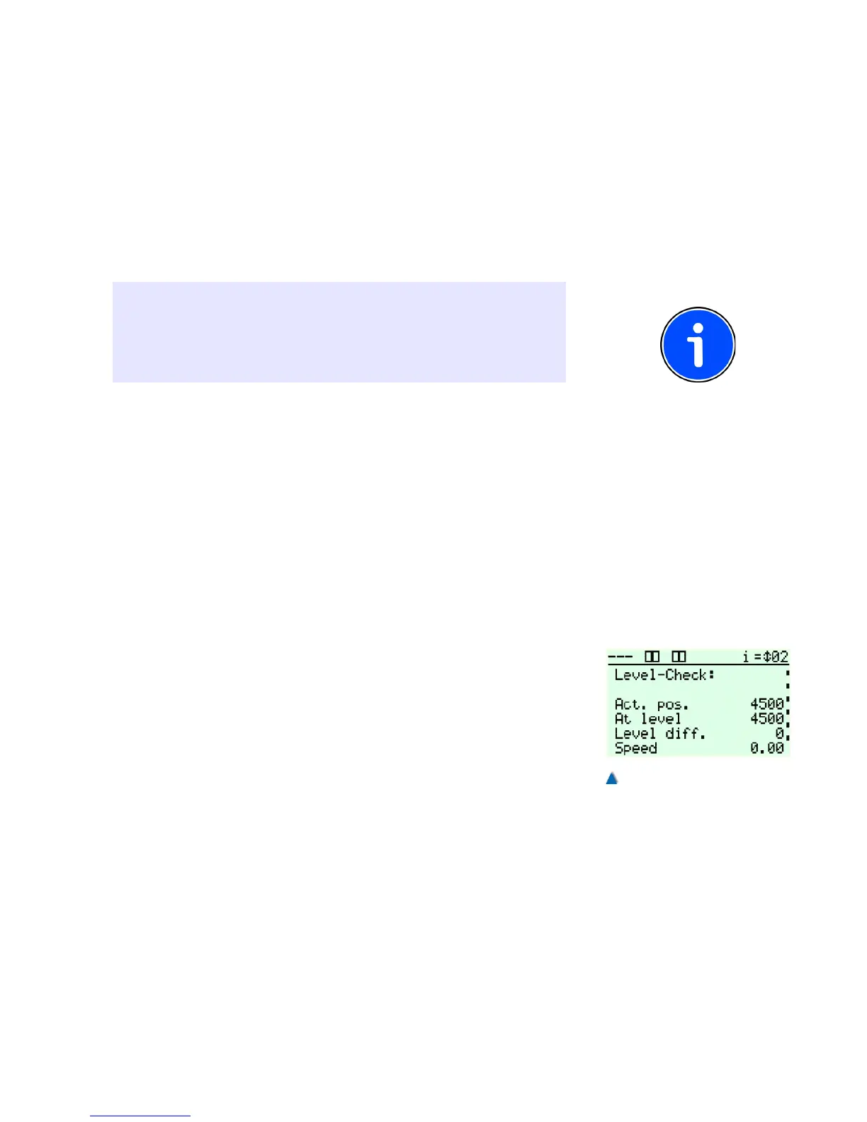
Move the lift to every landing from both directions and check whether
the car stops at the flush-landing levels. To do this, use the level con-
trol under DIAGNOSTICS > SHAFT SIGNALS > LEVEL CONTROL.
If the lift does not stop at the previously memorised position, you can
adjust the DECELERATION DISTANCE V0 (STOPPING DISTANCE)
under FUNCTIONS > DRIVE UNIT.
The range of the re-levelling area can be adjusted independently
from the flush-level area. Refer also to the service menu TIMES >
DRIVE UNIT / RELEVELLING DELAY TIME.
99