INFO!
• The electromagnetic blocking brake must be switched on and off
without time delay through relay MB, in order to ensure that the
inverter initiates smooth starts and stops.
• The main contactors to the motor must be switched on and off
without time delay through relay RB to ensure smooth starts and
stops .
• If the collective malfunction relay of the inverter becomes dislodged
due to a malfunction, the control unit must ensure that the mechan-
ical brake and main contactor to the motor are switched off imme-
diately. The output of the collective malfunction relay of the inverter
is connected to terminal 34 of the control unit.
• Together with the mains contactor of the inverter, the mains con-
tactor of the control unit has to be opened or closed without time
delay. This is the only way to monitor the brake chopper with
regard to excess temperature and disconnect the inverter from the
mains, if necessary.
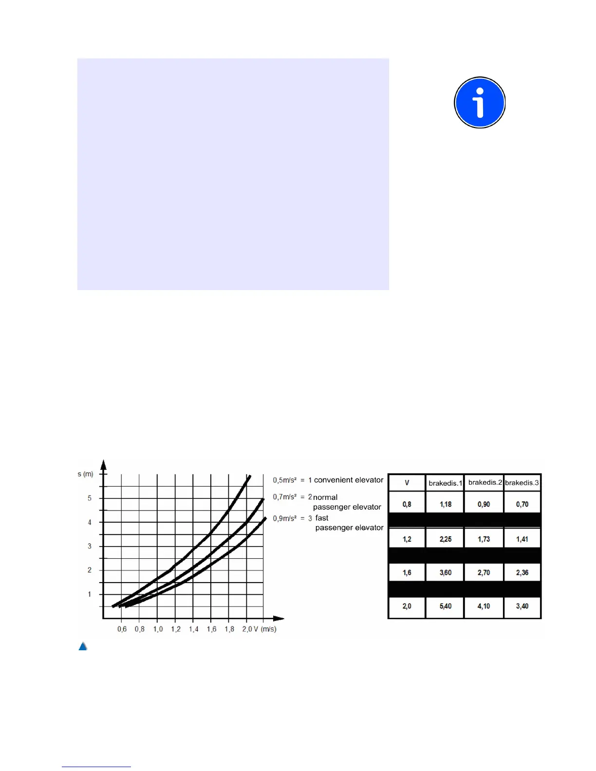
8.9.1 Disconnection Points for the High Travelling
Speed (V3)
The deceleration distance can be taken from the diagram. The values
shown are only valid if the factory set rounding R_NEG1=60% and
R_NEG2=90% are not changed. Moreover, it is assumed that the
control unit gives the disconnection points to the inverter without
delay.
The values shown are benchmark values only and should be adap-
ted to your individual requirements on site.
95