7.7 Electrical Installation
After having mounted all components, proceed to their electrical
installation according to the circuit diagrams. Properly connect all the
terminals and adhere to the EMC wiring directives.
7.8 Bus Connection
The lift control systems bp308 comes with the CAN Bus according to
application profile CiA-417. This profile describes the physical para-
meters of the bus lines as well as the topology. There are generally
special rules for the wiring of bus systems.
7.8.1 Electrical Bus Medium
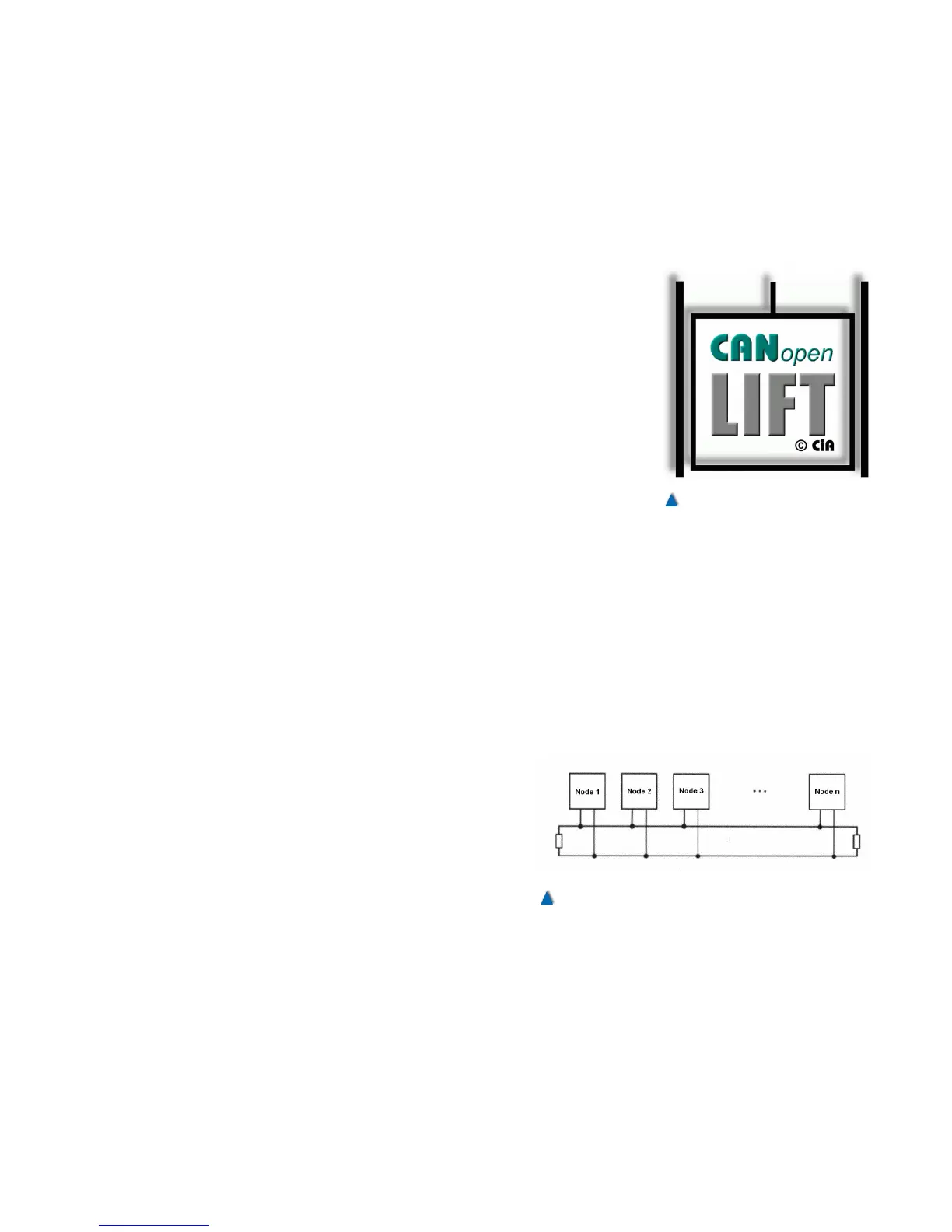
The components corresponding to CiA-417 require a two-wire data
communication line. Speaking in bus-terms, the components connec-
ted are denominated as nodes. Nodes are connected to the bus in
parallel. It must be ascertained that the topology of the bus line
always forms a line. The CAN high speed standard (ISO99-2)
requires both ends of the bus to be terminated with a resistor (120
Ohm) each. These terminations can be implemented in different
ways. It is possible within some nodes to activate an internal resist-
ance via a DIL switch or jumper, in other ones a resistor is to be con-
nected to the bus terminals. Read in the relating manuals of all con-
nected nodes how to realize the termination!
The driver modules used restrict the maximum amount of nodes
per bus to 64. If more nodes are required, it is neces-
sary to use repeaters or gateways (read further down).
Furthermore, all nodes connected must have identical
baud rates. The baud rate is preset to 250 kBit by net-
work master bp308 at the interfaces CAN1 and CAN2.
All the other components made by BÖHNKE + PART-
NER are equipped with an automatic baud rate identi-
fication or have been preset to a baud rate of 250 kBit.
Due to the baud rate used, length of the bus must not
exceed 250 m. Stub lines to the nodes must keep
below 3 m length.
61