7.3 Connection of Shielded Cables
To achieve an optimal electro-magnetic compatibility (EMC) of the lift
system, all shielded cables have to be connected according to the fol-
lowing illustrations, provided that they have not been manufactured
as EMC plug connectors .
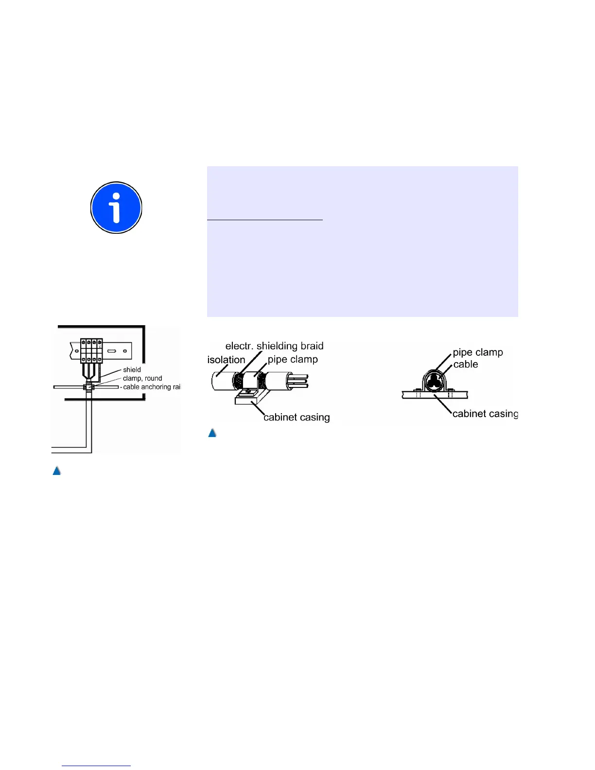
INFO!
It is not sufficient to twist the cable shielding and clip this »pigtail« to
PE potential. For a good EMC it is important to connect the shielding
always with its full surface .
If users connect further shielded cables at their own discretion, it is of
utmost importance that they connect them as shown in the illustra-
tions!
Follow the EMC instructions given by the manufacturer of the fre-
quency inverter at all times!
For any question concerning the EMC legislation please contact our
service team who will be pleased to advise you.
7.4 Designation of Circuit Diagrams
BÖHNKE + PARTNER define the different components in terms of
functional groups. We decided not to apply a fixed system when
naming the components. By preparing the circuit diagrams with a
CAD system, we achieve a high flexibility in designating the circuit
diagrams and parts lists. Each component is designated directly in
the circuit diagram with reference to function as well as project, i.e. in
a specific way for each customer.
Meanings of the abbreviations (functional groups):
A - Modules made by BÖHNKE + PARTNER, inverters
B -
C - Separate condensers
56 Installation Manual System »bp308« – Electrical Installation