8.11 Commissioning of the Floor selector System
As soon as it possible to travel with inspection control, the transmit-
ters of the Floor selector system can be mounted and installed. It can
be either magnet switches, absolute rotary shaft encoders (AWG-05)
or linear encoder systems such as USP or laser positioning systems.
8.11.1 Installation of the Deceleration Switches
ATTENTION!
For your personal safety, make sure that the inspection switch ON-
OFF as well as the buttons UP-DOWN and EMERGENCY STOP
have been wired into the safety circuit according to the circuit dia-
gram.
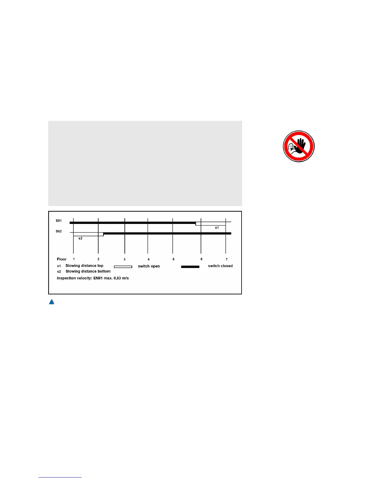
To decelerate the first travels even when the absolute encoder has
not yet been installed, first install the deceleration switches S81 and
S82 for inspection and emergency control at the terminal landings
putting them at their correct deceleration points in the well, and
ascertain that they switch properly.
Deceleration is initiated when the switches in the direction of travel
open accordingly. Deceleration switch S81 opens and starts deceler-
ation for the top landing. Deceleration switch S82 opens and starts
deceleration for the bottom landing. The deceleration of inspection
and emergency travels has to be carried out at these deceleration
points as well. The flush-level position of the terminal landings must
not be over-travelled.
Please set the following in the service menu:
> MAINTENANCE
97