> MAINTENANCE FUNCTIONS
Scroll through this sub-menu until you reach ENABLE ASSEMBLY
MODE and select ON. Now scroll further to ASSEMBLY MODE
WITH PRE-LIMIT SWITCHES (S81/S82) and select ON.
After that you can start travelling with inspection/emergency control in
order to install the Floor selector system as described in section 6.6.
8.11.2 Basic Settings
After installing the CAN transmitter system (see installation manual
enclosed), select the following presets in the bp308 setup menu:
Setup menu: > PARAMETER
> LIFT DATA
> FLOOR SELECTOR > ABSOLUTE ENCODER (CAN)
followed by: > PARAMETER
> FLOOR SELECTOR
> APS1 PARAMETER
TYPE
CODE SEQUENCE
Deceleration points and flush-level positions can comfortably be set
via special setting menus.
In the service menu, the following basic settings have to be selected:
Service menu: > SETTINGS
> FUNCTIONS
> DRIVE UNIT
> TRAVELLING SPEED
> DECLARATION DISTANCE
> MINIMUM TRAVEL DISTANCES
Enter the nominal and intermediate speeds of the system.
Go to this menu : > SETTINGS
> SHAFT ENCODING
> PARAMETER
> GENERAL WAYS
SHAFT PIT
SHAFT HEAD
CAR HEIGHT
Enter an approximate depth of the shaft pit, i.e. the distance between
the sill of the bottom landing and the floor of the shaft pit.
This value has been preset to 1 m at factory and is meant to obtain
the most precise well representation possible.
98 Installation Manual System »bp308« – Commissioning Instructions
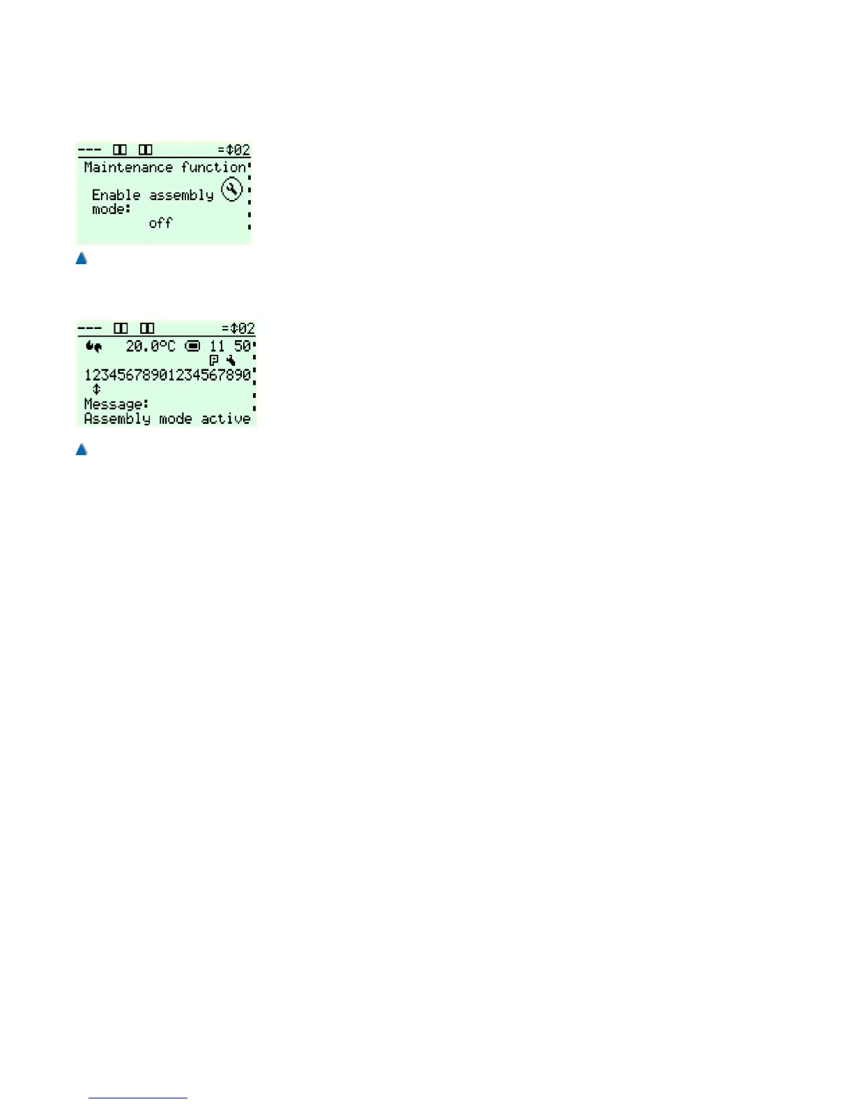
Fig. 62
Activating the assembly travel
to move the car without encoder
system.
Fig. 63
Information on the activated
assembly travel in the standard
view.