Control inputs (example)
GND Reference potential
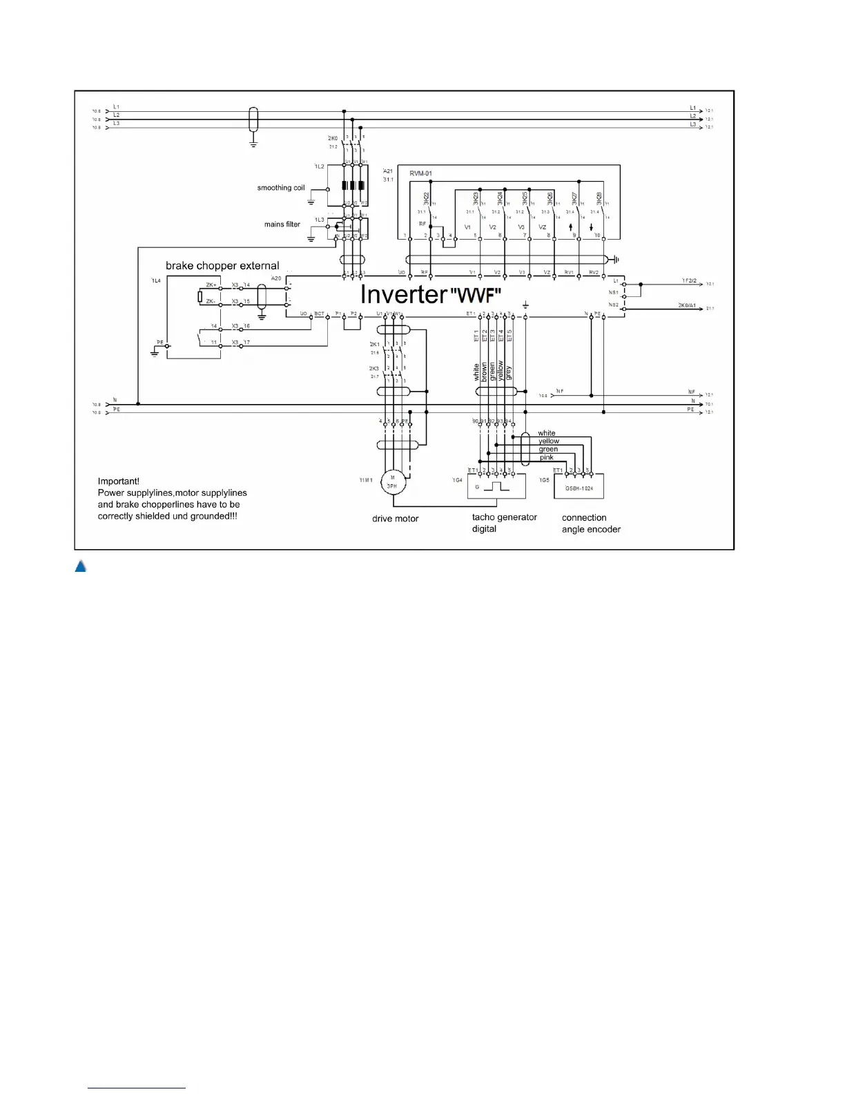
UO Control voltage of the inverter
voltage output selecting the inputs
RF Controller enabling, to be in selected status during travel .
V1 Fine positioning speed
V2 Levelling speed
V3 Travel speed
VZ Re-levelling speed
RV1 Direction default 1 UP
RV2 Direction default 2 DOWN
Provided that the inverter has been connected according to
the switching circuit suggestion, the factory preset motor
turns left if input »RV1« is activated and right if »RV2« is
activated (as seen from the motor side of the shaft.
ZE1 Additional speed V_ZE1
ZE2 Additional speed V_ZE2
72 Installation Manual System »bp308« – Electrical Installation