Status Indicator
LED Condition Denotation
On Trouble Condition:
– Grounding Conductor is not connected or there is a
communication failure between the module and the AMAX
panel
– No zones distributed
– Module address setting error
Stable flash Normal Operation
Off Power failure
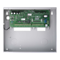
DX3010
General
The AMAX panel supports DX3010 output expansion modules. Each module supports 8 fully
programmable relay outputs.
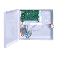
For information on the installation, refer to Module Installation, page 25.
Address Setting
Each DX3010 module connected to the AMAX panel needs its own data bus address.
Data Bus Address Outputs
150 5-12
151* 13-20
Table 5.7: DX3010 Address Settings
DIP Switch S1 S2 S3 S4 S5 S6
Data Bus Address 1 2 4 8 16 Mode
150 On On On On On Off
151* Off On On On On Off
Table 5.8: DX3010 DIP Switch Settings
* AMAX 3000 / 4000
Figure 5.5: DX3010 DIP Switch Settings
5.3.4
5.4
5.4.1
5.4.2
18 en | Optional Modules and Peripheral Devices AMAX 2100 / 3000 / 4000
2014.11 | 02 | F.01U.267.112 Installation Guide Bosch Sicherheitsysteme GmbH
 Loading...