24 en | CAN network Modular fire panel
07.2019 | 5.9 | F.01U.247.450 Networking guide Bosch Sicherheitssysteme GmbH
– Produce a configuration for the backbone in FSP-5000-RPS. Import all of the
necessary panel configurations. Configure the network settings and print them out.
– Connect all panels to a network.
– Configure the network settings for the individual control panels directly at the panel
controller as per the printout.
– Reset each of the control panels in order to load the network configuration.
– Ping the neighboring panels in order to check the network.
– Commission the entire backbone and rectify any errors.
Commission the sub-loops as per the example of the backbone.
Add a panel to a network
1. Change the network configuration in FSP-5000-RPS.
2. Print the network information out for safe keeping, or store the information on the
laptop.
3. Install the control panel and network cables and connect them to the network.
4. Configure the network settings for the individual control panel directly at the control unit
as per the printout.
5. Reset the panel and adjoining panels in order to activate the network configuration.
Remove a panel from the network
1. Change the network configuration in FSP-5000-RPS.
2. Print the network information out for safe keeping, or store the information on the
laptop.
3. Configure the network settings for the adjoining control panels directly at the control unit
as per the printout.
4. Shut off the panel, and the power supply (mains and battery) before removing it from the
network.
5. Reset the adjoining panels in order to activate the network configuration.
6 CAN network
Loop topology
In loop topology, the CAN cable is always routed from a CAN1 terminal to a CAN2 terminal
[CAN1 ⇒ CAN2]. The cable length depends on the cable cross-section.
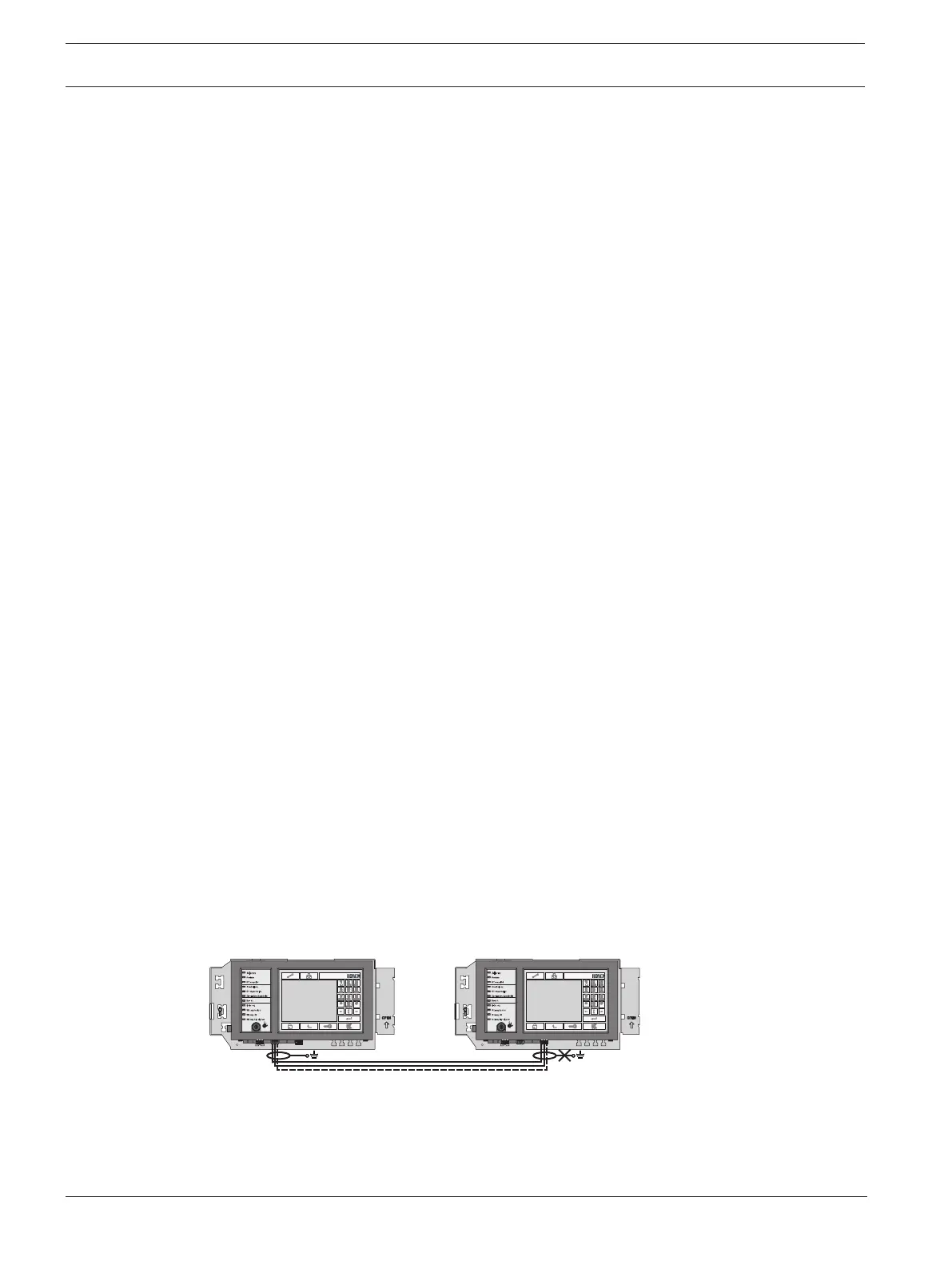
CAN connection
The CAN connection is a two-wire connection (CAN‑H and CAN‑L). Connect CAN‑H to CAN‑H
and connect CAN‑L to CAN‑L for a two-wire connection. A three-wire connection (CAN‑H,
CAN‑L and CAN‑GND) may be necessary in exceptional cases, e.g. with a high EMC load or a
significant difference in grounding potential. Connect CAN‑H to CAN‑H, CAN‑L to CAN‑L and
CAN‑GND to CAN‑GND for a three-wire connection. The shield wire of the CAN cable is only
connected to the metal housing of the panel on one side.
CAN1 H
CAN1 L
CAN1 G
CAN1 H
CAN1 L
CAN1 G
Figure6.1: CAN connection
Cable length for networking
The maximum permitted cable length depends on the loop resistance of the cable used and on
the number of communicating.

 Loading...


