50 en | Cabling Modular fire panel
07.2019 | 5.9 | F.01U.247.450 Networking guide Bosch Sicherheitssysteme GmbH
– If you have connected a redundant power supply or are creating a switch-to-switch
connection, then the fault outputs of the RSTP switch must be monitored via panel
inputs. For example, use the inputs on the panel controller or IOP 0008 A.
– In the case of the media converter, the Link Fault Pass-Through function must be
activated. Configuration is performed via the DIP switch of the media converter.
Notice!
Use only the following cables for networking:
Ethernet cable
Ethernet patch cable, shielded, CAT5e or better.
Please note the minimum bending radii specified in the cable specification.
Fiber optic cable
Multi-mode: fiber optic Ethernet patch cable, duplex I‑VH2G 50/125μ or duplex I‑VH2G
62.5/125μ, SC plug.
Single mode: fiber optic Ethernet patch cable, duplex I-VH2E 9/125μ, SC plug.
Please note the minimum bending radii specified in the cable specification.
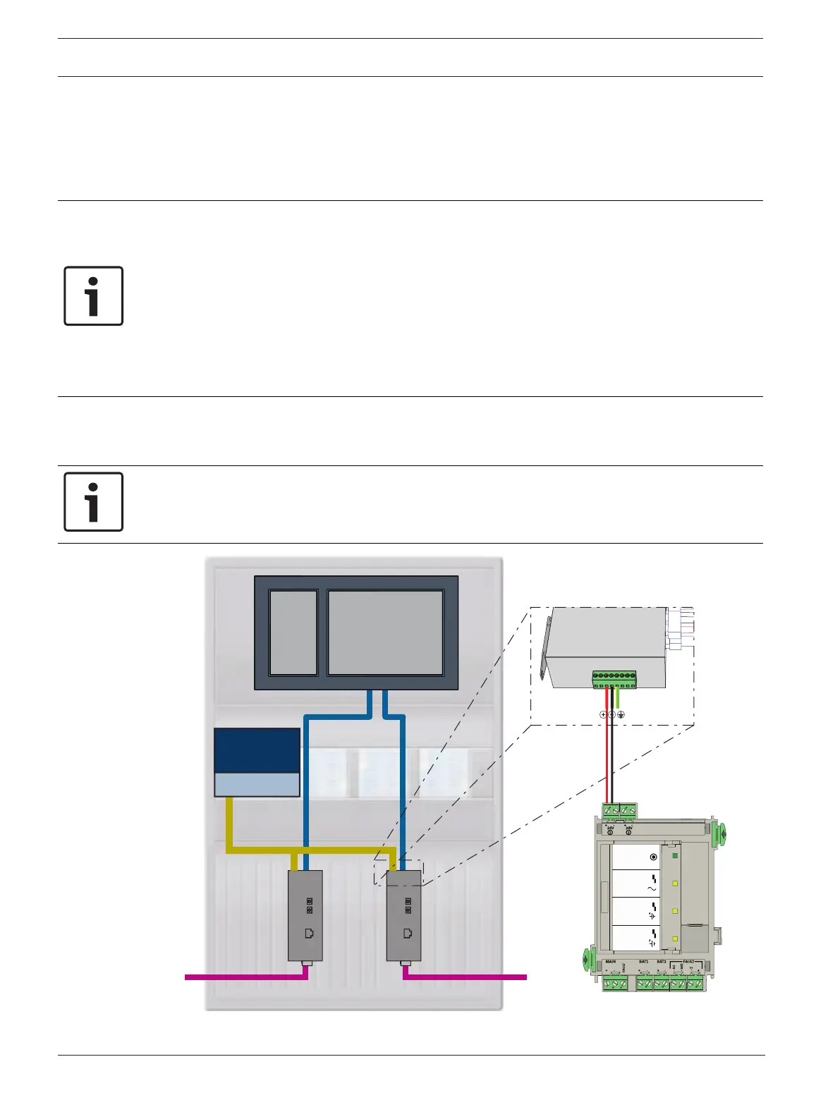
11.1 Media converter
Connection of media converters
Notice!
Note the direction of transmission of the FOC fibers when connecting the FX cabling of the
media converters.
BCM-0000-B
24V
24V (2,8 A)
MAIN POWER
MAIN POWER
TROUBLE
TROUBLE
TROUBLE
BATTERY 1
BATTER
Y 2
BCM-0000-B
Figure11.1: Connection of media converter to power supply and to panel controller IN1/IN2

 Loading...


