Modular fire panel Cabling | en 49
Bosch Sicherheitssysteme GmbH Networking guide 07.2019 | 5.9 | F.01U.247.450
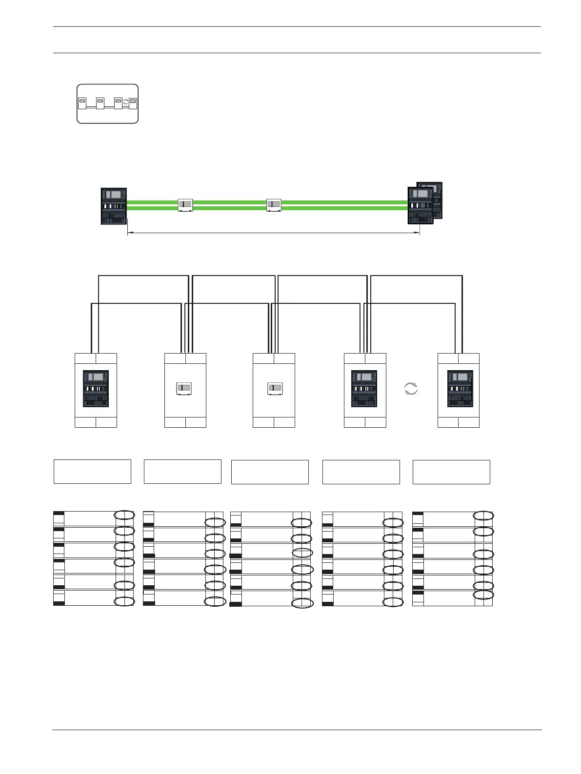
Stub with redundant network and redundant panel
CAN internal
001
Redundant-PCTRL
PCTRL is
CAN2 Ground Fault
Detection
CAN1 Ground Fault
Detection
1
On
On
On
On
On
On
CAN1 Termination
CAN1_GND CAN2_GND
CAN2 Termination
Connection
No
No
No
No
No
No
Off
Off
Off
Off
Off
Off
Yes
Yes
Yes
Yes
Yes
Yes
2
3
4
5
6
x100
x10 x1
Network Address: ________
004
Redundant-PCTRL
PCTRL is
CAN2 Ground Fault
Detection
CAN1 Ground Fault
Detection
1
On
On
On
On
On
On
CAN1 Termination
CAN1_GND CAN2_GND
CAN2 Termination
Connection
No
No
No
No
No
No
Off
Off
Off
Off
Off
Off
Yes
Yes
Yes
Yes
Yes
Yes
2
3
4
5
6
x100
x10 x1
Network Address: ________
004
Redundant-PCTRL
PCTRL is
CAN2 Ground Fault
Detection
CAN1 Ground Fault
Detection
1
On
On
On
On
On
On
CAN1 Termination
CAN1_GND CAN2_GND
CAN2 Termination
Connection
No
No
No
No
No
No
Off
Off
Off
Off
Off
Off
Yes
Yes
Yes
Yes
Yes
Yes
2
3
4
5
6
x100
x10 x1
Network Address: ________
002
1
On
On
On
On
On
On
CAN1 Termination
CAN1_GND CAN2_GND
CAN2 Termination
NA
NA
NA
Connection
No
No
No
No
No
No
Off
Off
Off
Off
Off
Off
Yes
Yes
Yes
Yes
Yes
Yes
2
3
4
5
6
x100
x10 x1
Network Address: ________
003
1
On
On
On
On
On
On
CAN1 Termination
CAN1_GND CAN2_GND
CAN2 Termination
NA
NA
NA
Connection
No
No
No
No
No
No
Off
Off
Off
Off
Off
Off
Yes
Yes
Yes
Yes
Yes
Yes
2
3
4
5
6
x100
x10 x1
Network Address: ________
001
002
004 004
L
max
003
CAN1 CAN2
ETH1 ETH2
CAN1 CAN2
ETH1 ETH2
CAN1 CAN2
ETH1 ETH2
CAN1 CAN2
ETH1 ETH2
CAN1 CAN2
ETH1 ETH2
Figure10.7: Stub with redundant network and redundant panel
11 Cabling
To create an EN 54-2-compliant system, connect the RSTP switches and the media converters
via the monitored power supply of the fire alarm control panel.
– For the power supply to the media converters and to the RSTP switches use the 24 V
output of either the BCM 0000 B or FPP-5000.

 Loading...


