14 en | Topologies Modular fire panel
07.2019 | 5.9 | F.01U.247.450 Networking guide Bosch Sicherheitssysteme GmbH
Notice!
FSP-5000-RPS programming software
You must assign an OPC server to each network node from which statuses should be
transmitted.
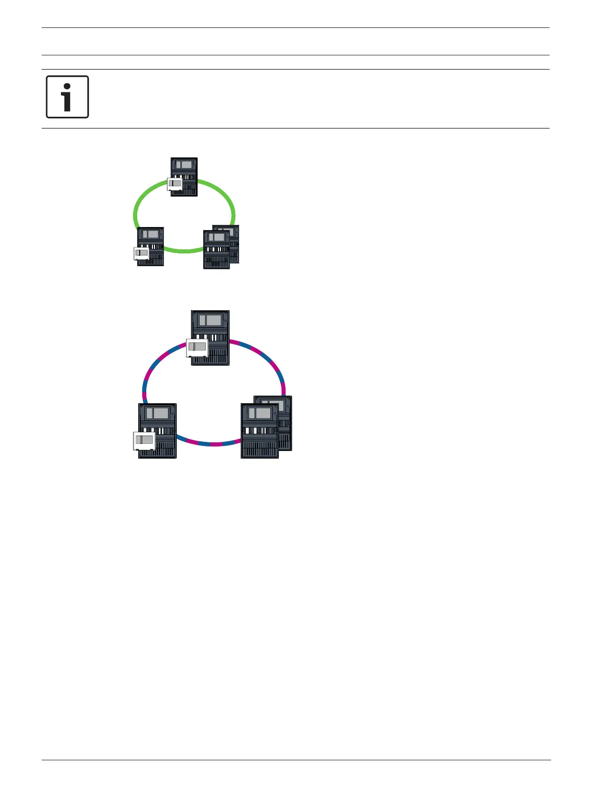
4.1 CAN loop
Figure4.2: CAN loop
4.2 Ethernet loop
Figure4.3: Ethernet loop
4.3 Ethernet loop with OPC server
Ethernet switch for connecting the OPC server must be programmed separately
Program the IP address and redundancy settings of the Ethernet switch, see Settings on
switch, page 39. As the switch is installed in the immediate vicinity (without intermediate
space), the power supply does not have to be designed redundantly and the fault outputs are
therefore not used.
Make sure that the RSTP settings in the panel controllers, in FSP-5000-RPS and in the
Ethernet switch are identical.
OPC server must be programmed separately
Program the IP address, network nodes, network group and RSN. See the corresponding
section in the Installation chapter of the Networking Guide.
The OPC server uses port 25000 as standard.
Make sure that the settings in the FSP-5000-RPS programming software and in the OPC server
are identical.
Parameters
– The OPC server may be connected via an Ethernet cable (copper) or fiber optic cable.

 Loading...


