Modular fire panel CAN network | en 25
Bosch Sicherheitssysteme GmbH Networking guide 07.2019 | 5.9 | F.01U.247.450
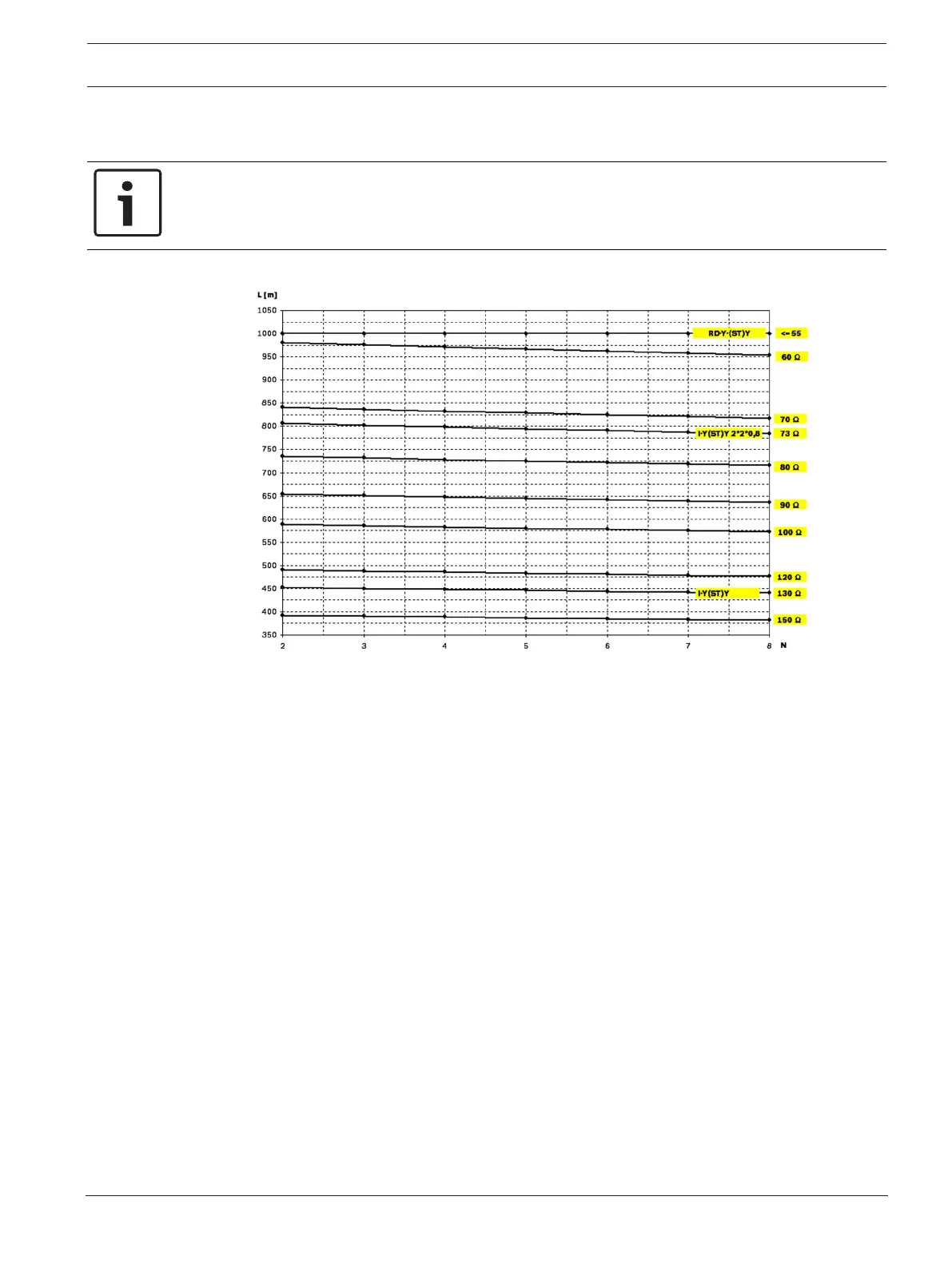
Example: The J-Y (St) Y 2 x 2 x 0,8 mm red fire detector cable enables two nodes with a
maximum distance of around 800 m to be connected.
Notice!
The distance between two nodes in loop topology can be determined by reading off the value
at two nodes in the diagram.
Figure6.2: CAN network: Achievable cable length, depending on the number of nodes and the cable
resistance
L = cable length in meters
N = number of nodes
6.1 Creating or modifying a CAN network
This procedure is suitable for projects involving only a small number of engineers working on
the installation of the fire alarm system concurrently.
Procedure for creating a CAN network
1. Plan out the network.
2. Create the network in FSP‑5000‑RPS.
3. Print the network information out for safe keeping, or store the information on the
laptop.
4. Install the control panels and connect them with CAN cables to a network.
5. Connect your computer with the FSP‑5000‑RPS programming software to a control panel
in the network. Load this configuration to all other control panels across the network via
this control panel. Redundant panels use the configuration of the main panel.
6. Carry out a reset in order to reset the pending error messages. Rectify any errors.

 Loading...


