Modular fire panel Cabling | en 51
Bosch Sicherheitssysteme GmbH Networking guide 07.2019 | 5.9 | F.01U.247.450
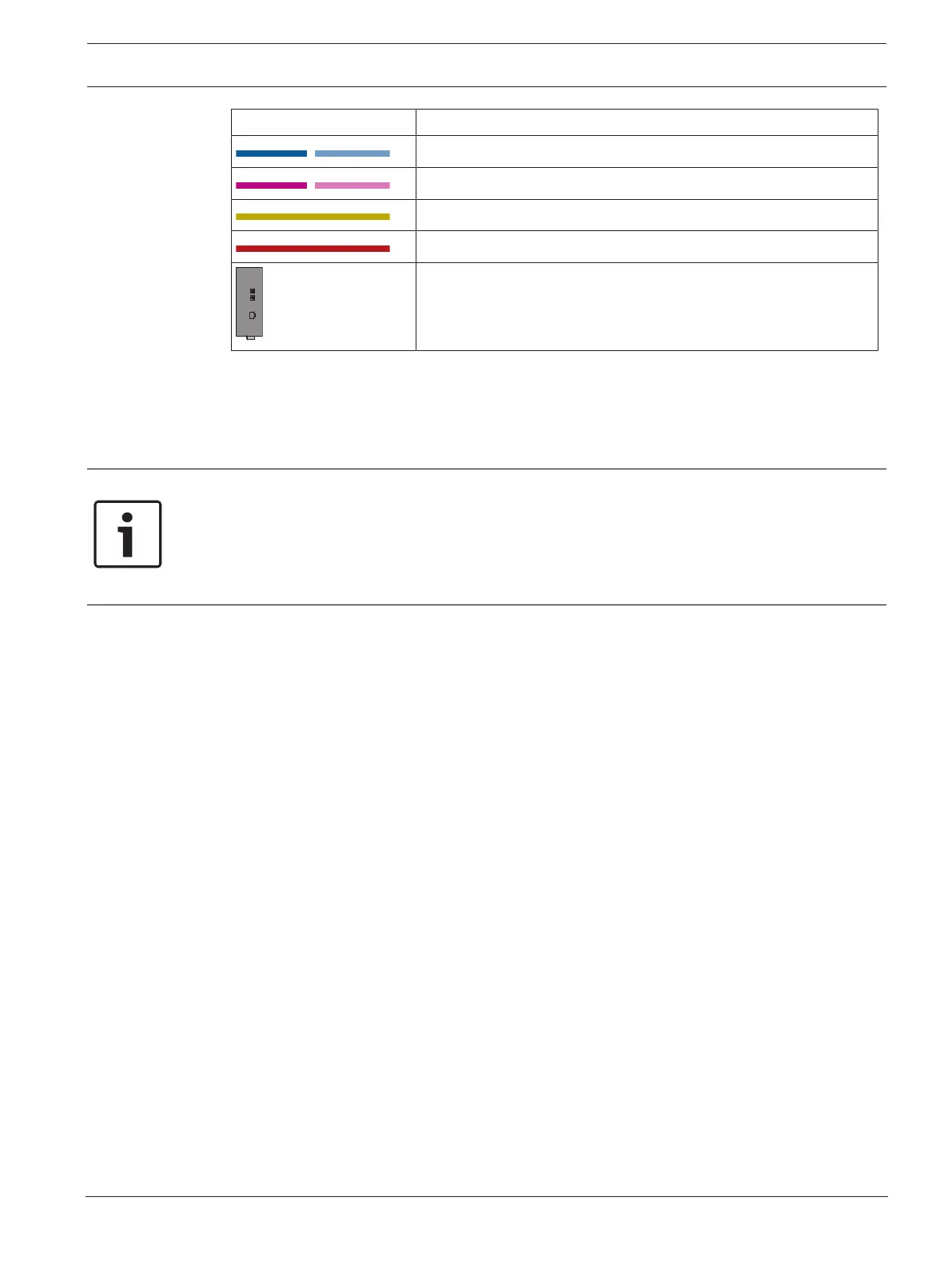
Icon Description
TX Ethernet cable (copper)
FX Ethernet cable (fiber optic cable)
24 V power supply
Transmission of fault
Media converter
11.2 Ethernet switch
Connection of switch
You can connect the fault outputs of the switches to the inputs of the panel controller or an
IOP input and output module.
Notice!
The fault relay only has to be connected for applications where at least one of the following
requirements is met:
There is a connection between 2 switches. This is possible in the case of a backbone with
sub-loops, for example.
The power supply to the switch is designed redundantly.

 Loading...


