EasyManuals Logo

Bosch FPA-5000 Networking Guide

Bosch FPA-5000
66 pages
To Next Page IconTo Next Page
To Previous Page IconTo Previous Page
Page #52 background imageLoading...
Page #52 background image
52 en | Cabling Modular fire panel
07.2019 | 5.9 | F.01U.247.450 Networking guide Bosch Sicherheitssysteme GmbH
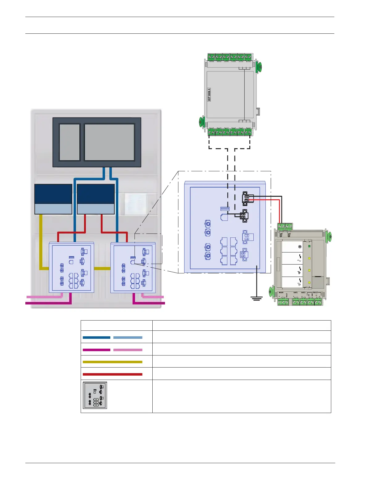
Connection of switches with reporting of faults to the inputs of the IOP module:
BCM-0000-B
24V
IOP 0008 A
Input Input
-
+
24V (2,8 A)
MAIN POWER
MAIN POWER
TROUBLE
TROUBLE
TROUBLE
BATTERY 1
BATTER
Y 2
BCM-0000-B
IOP 0008 A
IN1
IN2
IN3
IN4
IN5
IN6
IN7
IN8
GND
GND
GND
GND
OUT1
OUT2
OUT3
OUT4
OUT5
OUT6
OUT7
OUT8
GND
GND
GND
GND
Figure11.2: Connection of switch to the power supply and IOP
Icon Description
TX Ethernet cable (copper)
FX Ethernet cable (fiber optic cable)
24 V power supply
Transmission of fault
RSTP switch

Other manuals for Bosch FPA-5000

Questions and Answers:

Question and Answer IconNeed help?

Do you have a question about the Bosch FPA-5000 and is the answer not in the manual?

Bosch FPA-5000 Specifications

General IconGeneral
Max Number of Detectors per Loop254
DisplayLCD
Network CapabilityYes
Power Supply24 V DC
Operating Temperature-5°C to +50°C
Communication PortsEthernet
Humidity Range95% non-condensing

Related product manuals