Modular fire panel Remote Services | en 35
Bosch Sicherheitssysteme GmbH Networking guide 07.2019 | 5.9 | F.01U.247.450
Protocol Default port Description
IPsec VPN UDP 500 and UDP 4500 for Remote Connect
3. Connect the LAN1 port of the Secure network gateway to the designated Ethernet port of
the panel controller using the supplied CAT5 RJ45 network cable. Observe the possible
topologies.
4. Connect the Secure network gateway to a 100 V - 230 V mains supply using the supplied
power supply.
WAN LED on (blue), when the connection to the internet has been established. VPN LED on
(blue) shortly after, which indicates that a VPN connection to the Remote Portal has been
established.
Each connected panel or panel network has one unique System ID.
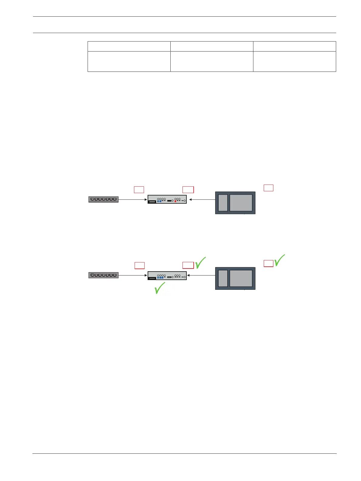
Separating sub-networks (VPN LED off)
Connecting the Secure network gateway for Remote Services fails in case of overlapping sub-
networks (VPN LED off). The following example shows a Secure network gateway and a panel
controller in the same address range as the DSL router.
DSL router
192.168.1.12
(via DHCP)
DSL router
192.168.1.254
192 .168.1.12.
(via DHCP)
192.168.2.254
192.168.2.1
192.168.1.1
!
!
!
A Secure network gateway detects overlapping sub-networks unambiguously: The Alarm LED
is blinking continuously.
Separating the sub-networks is done by changing the third octet of the IP address. You change
the IP addresses on panel network side. After changing the IP address you have to propagate
the changes to the Secure network gateway. To do so, launch the web interface via a web
browser:
- Address: https://192.168.1.254
- User name: bosch
- Password: ipti83
Under Configuration -> Network (LAN) you can change the IP address. Consider, that the
Default gateway: address in the panel controller configuration must match the IP address of
the Secure network gateway.
Step 3: Establish remote connection
1. At the panel use standard Ethernet settings.
2. Restart the panel.

 Loading...


