Modular fire panel Installation | en 43
Bosch Sicherheitssysteme GmbH Networking guide 07.2019 | 5.9 | F.01U.247.450
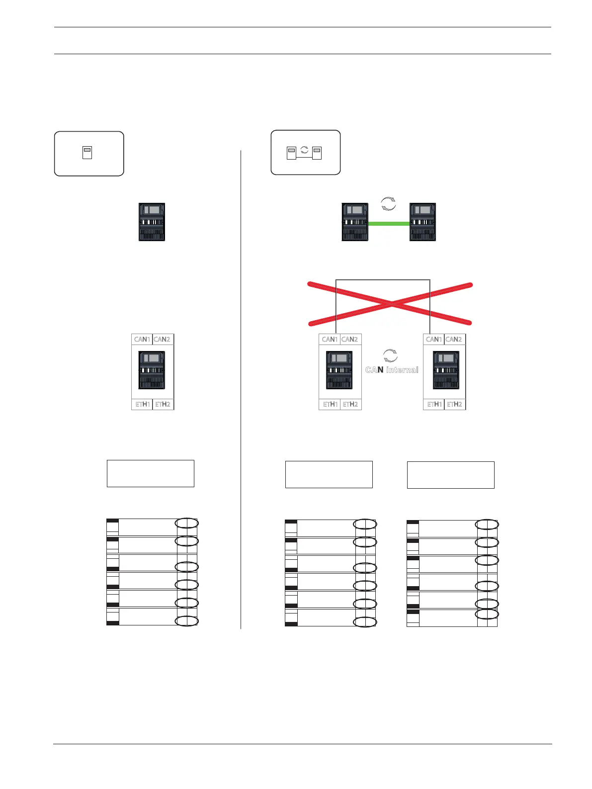
Configuration of the topology
The DIP switches for the configuration of different topologies are located on the rear.
4 Mark the selected setting on the sign near to the DIP switches.
Standalone Panel and Redundant Standalone Panel
001001
001
CAN1 CAN2
ETH1 ETH2
CAN1 CAN2
ETH1 ETH2
CAN internal
CAN1 CAN2
ETH1 ETH2
001
Redundant-PCTRL
PCTRL is
CAN2 Ground Fault
Detection
CAN1 Ground Fault
Detection
1
On
On
On
On
On
On
CAN1 Termination
CAN1_GND CAN2_GND
CAN2 Termination
Connection
No
No
No
No
No
No
Off
Off
Off
Off
Off
Off
Yes
Yes
Yes
Yes
Yes
Yes
2
3
4
5
6
x100
x10 x1
Network Address: ________
001
Redundant-PCTRL
PCTRL is
CAN2 Ground Fault
Detection
CAN1 Ground Fault
Detection
1
On
On
On
On
On
On
CAN1 Termination
CAN1_GND CAN2_GND
CAN2 Termination
Connection
No
No
No
No
No
No
Off
Off
Off
Off
Off
Off
Yes
Yes
Yes
Yes
Yes
Yes
2
3
4
5
6
x100
x10 x1
Network Address: ________
Network Address: ________
001
Redundant-PCTRL
PCTRL is
CAN2 Ground Fault
Detection
CAN1 Ground Fault
Detection
1
On
On
On
On
On
On
CAN1 Termination
CAN1_GND CAN2_GND
CAN2 Termination
Connection
No
No
No
No
No
No
Off
Off
Off
Off
Off
Off
Yes
Yes
Yes
Yes
Yes
Yes
2
3
4
5
6
x100
x10 x1
Figure10.1: Standalone panel (regular and redundant): Configuration in network

 Loading...


