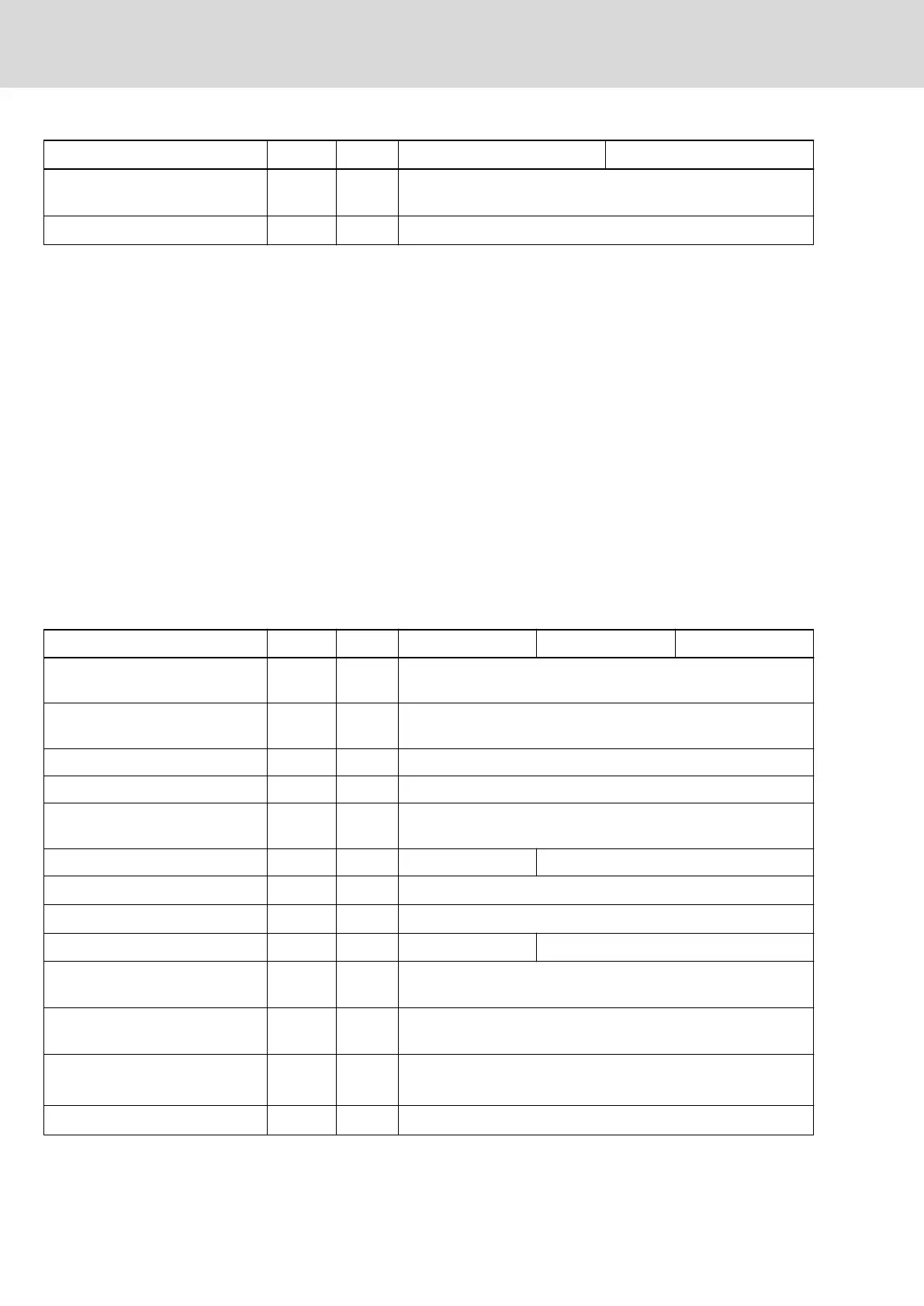
Description Symbol Unit XCS1-W0100 XCS1-W0120
Maximum allowed DC bus power
(U
LN AC 400V
)
P
out
kW 47
Output frequency range
12)
f
out
Hz 0 ... 1600
1) 2) 3) Housing dimensions
4) 5) 6) See fig. "Air intake and air outlet at device"
7) Observe supply voltage for motor holding brake
8) See information on "Rated power consumption control voltage
input at U
N3
"
9) Mains input L1, L2, L3; For use on a solidly grounded wye
source only.
10) Use listed AC input line fuses (class J; 100 A). Suitable for use
on a circuit capable of delivering not more than 42000 rms
symmetrical amperes, 500 Volts maximum. If using inverse-
time circuit breakers or type E combination motor controllers in‐
stead of recommended fuses, see UL 61800-5-1, section
5.2.3.6.2DV.4.1.3
11) Copper wire; PVC-insulation (conductor temperature 75 °C;
T
a
≤ 40 °C) in accordance with NFPA 79 chapter 12 and
UL 508A chapter 28
12) Depending on switching frequency which was set in parameter
P‑0‑0001
Tab. 7-1: UL ratings and dimensions
UL ratings and dimensions (XMD1)
Description Symbol Unit XMD1-W2323 XMD1-W5454 XMD1-W7070
Listing in accordance with UL
standard
UL 61800-5-1
Listing in accordance with CSA
standard
C22.2 No. 274-17
UL files E134201
Pollution degree 2
Ambient temperature range with
nominal data
T
amax
°C 40
Mass m kg 3.3 6.7
Device height
1)
H mm 309
Device depth
2)
T mm 196.5
Device width
3)
B mm 50 150
Minimum distance on the top of
the device
4)
d
top
mm 80
Minimum distance on the bottom
of the device
5)
d
bot
mm 80
Horizontal spacing at the device
6)
d
hor
mm
0 (for devices in the DC bus group)
10 (for devices outside of the DC bus group)
Rated control voltage input
7)
U
N3
V 24
32/123
Technical data
IndraDrive X Drive Controllers Power Sections XCS1, XMD1,
XMQ1
Bosch Rexroth AG R911392532_Edition 01