Motor temperature monitoring, motor holding brake
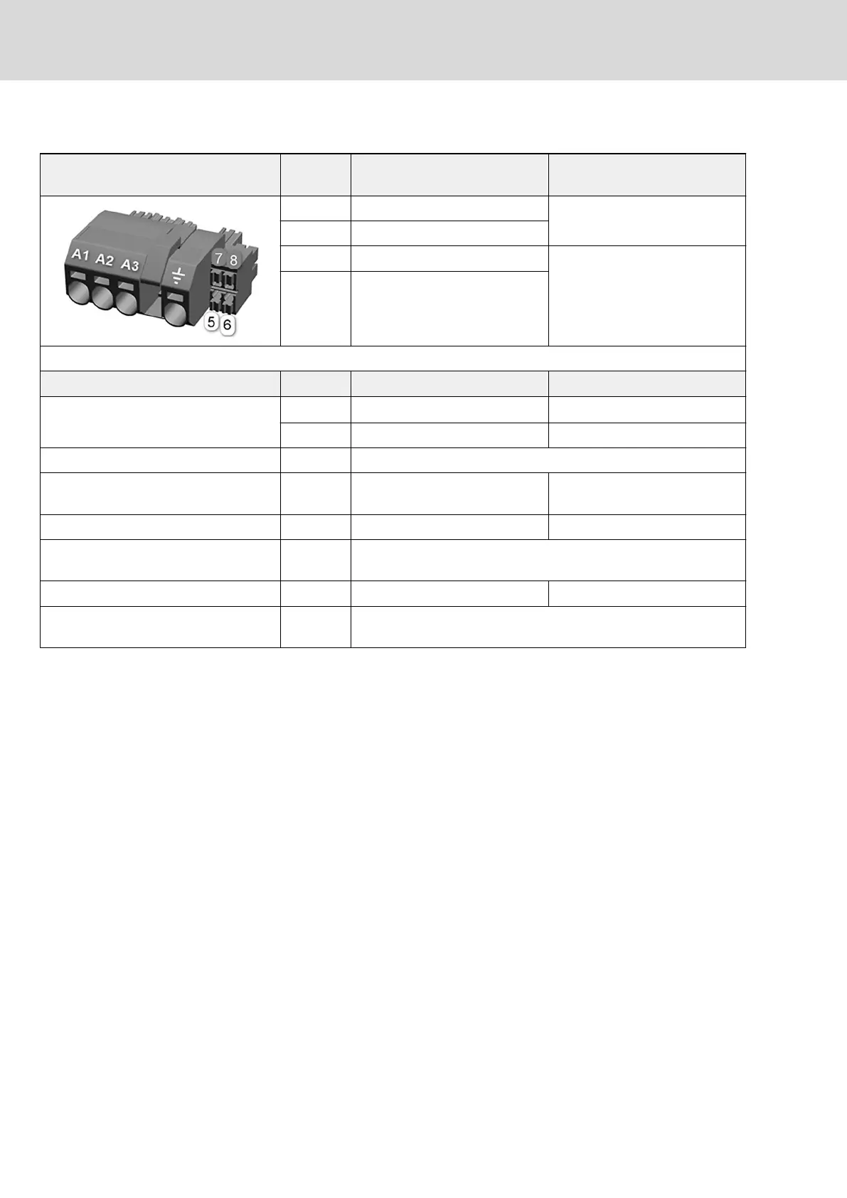
View Connectio
n
Signal name Function
5 MotTemp+ Motor temperature evaluation
input
6 MotTemp-
7 +24VBr Output for controlling the motor
holding brake
8 0VBr
Spring terminal (connector) Unit min. max.
Connection cable
Stranded wire
mm
2
0.14 1.5
AWG 26 16
Stripped length mm 8
Current carrying capacity of brake
outputs
A - 1
Time constant of load ms - 50
Number of switching operations at
maximum time constant of load
Wear-free electronic contact
Switching frequency Hz - 0.5
Short circuit protection XZ03.7 against XZ03.8 (output for controlling the motor holding
brake)
Tab. 10-12: Function, pin assignment
Motor holding brake: Notes on in‐
stallation
Make sure the power supply is sufficient for the motor holding brake at the
motor. Observe that voltage drops on the supply line. Use connection lines
with the largest possible cross section of single strands.
Use an external contact element in accordance with the required safety
category if you wish to supply motor holding brakes with higher currents than
the current load allowed at the connection point. Make sure to comply with
the required minimum current consumption of 100 mA when using an
external contact element. Otherwise the brake current monitor will signal an
error.
78/123
Mounting, dismounting and electrical installation
IndraDrive X Drive Controllers Power Sections XCS1, XMD1,
XMQ1
Bosch Rexroth AG R911392532_Edition 01
 Loading...