EasyManuals Logo

Brocade Communications Systems DCX 8510-8 User Manual

Brocade Communications Systems DCX 8510-8
190 pages
To Next Page IconTo Next Page
To Previous Page IconTo Previous Page
Page #18 background imageLoading...
Page #18 background image
NOTE
Airow is from the nonport side to the port side and out the exhaust
vent.
1. Exhaust vent
2. Core switch blade (CR16-8)
3. Control processor blade (CP8)
4. FC16-32 port blade
5. Cable management comb
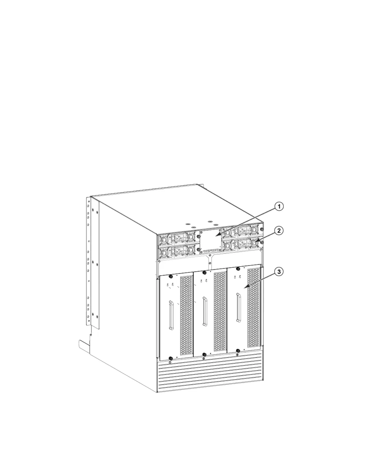
Nonport side view of the device
The following gure shows a sample conguration of the nonport side view of the Brocade DCX 8510-8.
FIGURE 2 Nonport side of the Brocade DCX 8510-8 (sample conguration)
1. WWN bezel (logo plate - WWN card behind)
2. Power supply
3. Blower assembly
Hardware components
Brocade DCX 8510-8 Backbone Hardware Installation Guide
18 53-1002180-15

Table of Contents

Other manuals for Brocade Communications Systems DCX 8510-8

Questions and Answers:

Question and Answer IconNeed help?

Do you have a question about the Brocade Communications Systems DCX 8510-8 and is the answer not in the manual?

Brocade Communications Systems DCX 8510-8 Specifications

General IconGeneral
BrandBrocade Communications Systems
ModelDCX 8510-8
CategorySwitch
LanguageEnglish

Related product manuals