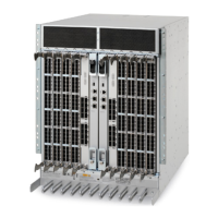
Managing cables
Cables can be organized and managed in a variety of ways, for example, using cable channels on the port sides of the cabinet or patch
panels to minimize cable management.
With the vertical orientation of the blades in the Brocade DCX 8510-8, a cable management comb is provided below the blades on the
port side.
Following is a list of recommendations:
• Leave at least 1 m (3.28 ft) of slack for each port cable. This provides room to remove and replace the device, allows for
inadvertent movement of the rack, and helps prevent the cables from being bent to less than the minimum bend radius.
• The minimum bend radius should be no smaller than ten times the cable radius. The minimum radius to which a 50 micron
cable can be bent under full tensile load is 5.1 cm (2 in.). For a cable under no tensile load, that minimum is 3.0 cm (1.2 in.).
• If ISL Trunking is in use, group the cables by trunking group. The ports are color-coded to indicate which ports can be used in
the same ISL Trunking group: eight ports marked with solid black ovals alternate with eight ports marked with oval outlines.
• Generally, Velcro
®
type cable restraints are recommended to avoid creating sharp bends in the cables. Do not use tie wraps with
optical cables because they are easily overtightened and can damage the optic bers.
• For easier maintenance, label the ber-optic cables and record the devices to which they are connected.
• Do not route cables in front of the air exhaust vents.
• Route the cables to the bottom of the Brocade DCX 8510-8 through the cable management comb.
• Keep LEDs visible by routing port cables and other cables away from the LEDs.
NOTE
Refer to "Cabling Best Practices" (available at http://www.brocade.com ) for cable management guidelines.
For the procedure to install the ICL cables, refer to Installing inter-chassis links (ICLs) on page 46
Verifying correct operation and backing up the conguration
To verify correct operation and back up the device conguration, follow these steps. For information about LED patterns, refer to
information on determining the status of extension, application, or port blades in the "System Monitoring" section.
Complete the following steps to back up the conguration for the device.
1. Check the LEDs to verify that all components are functional.
2. If necessary, log in to the switch by Telnet, using the admin account.
3. Verify the correct operation of the device by entering the switchShow command from the workstation. This command provides
information about switch and port status.
4. Verify the correct operation of the device in the fabric by entering the fabricShow command from the workstation. This
command provides general information about the fabric.
5. To back up the conguration, run the following two steps:
a) Enter the congupload -vf command. This command uploads the device's virtual fabric data.
b) Enter the congupload command. This command uploads the device conguration.
Managing cables
Brocade DCX 8510-8 Backbone Hardware Installation Guide
68 53-1002180-15

 Loading...