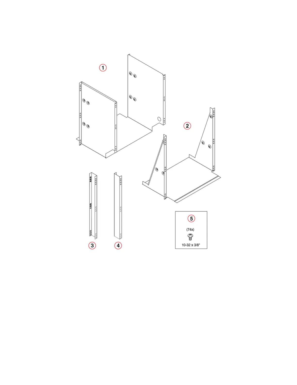
FIGURE 8 Rack kit parts
1. Tray, front, mid-mount, chassis
2. Tray, rear, mid-mount, chassis
3. Adapter, rear, mid-mount, right
4. Adapter, rear, mid-mount, left
5. Screw, 10-32 x 3/8”, pan head Phillips, ST, zinc (requires a torque of 32
inch-pounds)
NOTE
Not all parts may be used with certain installations depending on the device type.
Assembling the rack hardware
Perform the following steps to assemble the rack hardware.
1. Attach the rear tray (with or without adapter, as required) to both rack rails. Orient the tray (refer the following gure) and use nine
screws (Item E) for each rail.
2. Attach the front tray to both rack rails. Orient the tray (Figure 10) and use nine screws (Item E) for each rail.
Installing the 14U Chassis Mid-Mount Rack Kit for Two-Post Racks (XBR-DCX-0121)
Brocade DCX 8510-8 Backbone Hardware Installation Guide
53-1002180-15 39

 Loading...