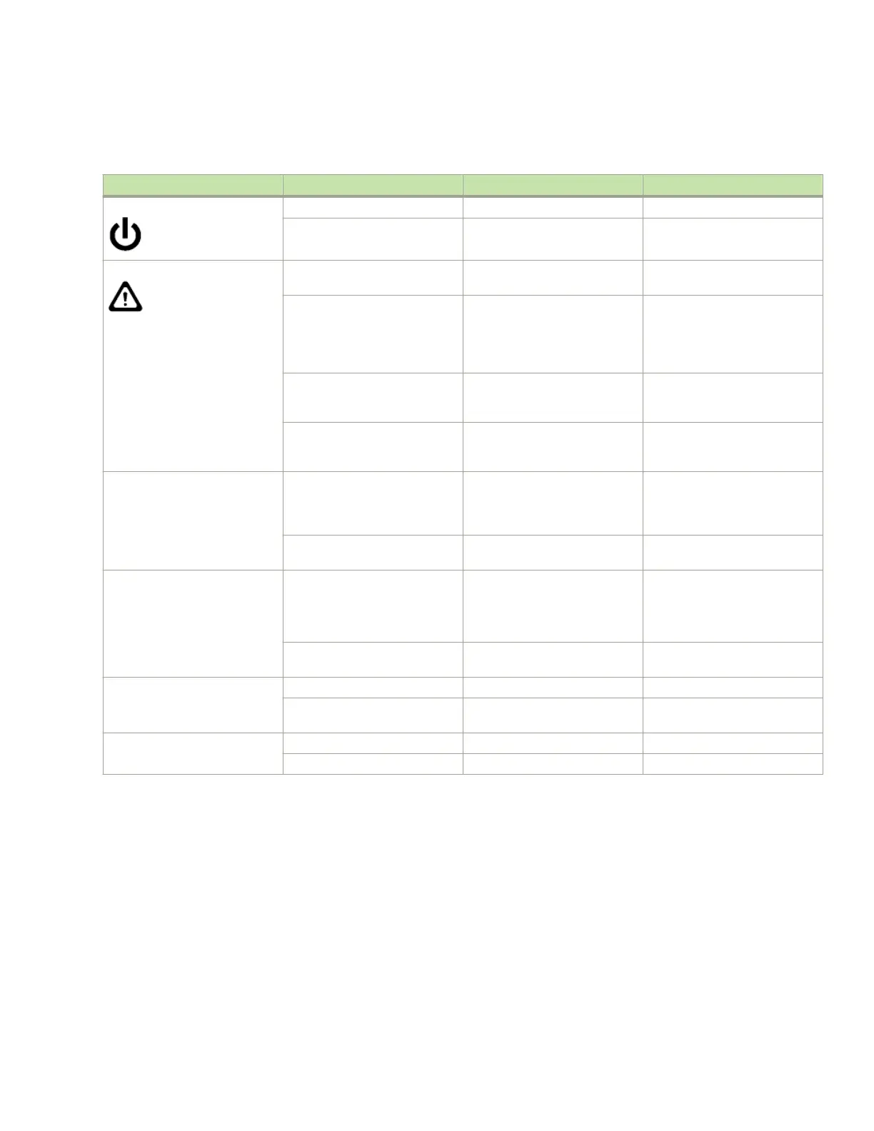
The following table describes the CP blade LED patterns and the recommended actions for those patterns.
TABLE 11 CP blade LED descriptions
LED purpose Color Status Recommended action
Power Steady green CP blade is on. No action required.
No light (LED is o) CP blade is not on. Ensure that the blade is rmly
seated and has power.
Status No light (LED is o) CP blade is either healthy or
does not have power.
Verify that the power LED is on.
Steady amber CP blade is faulty or the switch is
still booting.
Ensure that the blade is rmly
seated and the switch has
completed booting. If LED
remains amber, consult the
device supplier.
Slow-ashing amber (on 2
seconds, then o 2 seconds)
CP blade is not seated correctly
or is faulty.
Pull the blade out and reseat it. If
the LED continues to ash,
replace the blade.
Fast-ashing amber (on 1/2
second, then o 1/2 second)
Environmental range exceeded. Check for out-of-bounds
environmental condition and
correct it.
Ethernet Link Status No light (LED is o) Either an Ethernet link is not
detected, or it does not have
incoming power.
Ensure that the blade has power,
the Ethernet cable is rmly
seated, and the connected device
is functioning.
Flickering green/amber Ethernet link is healthy and trac
is owing through port.
No action required.
Ethernet Link Speed No light (LED is o) Ethernet link speed is 10 Mb/s
or CP blade does not have
incoming power.
Ensure that the CP has power.
NOTE: To force a persistent
Ethernet link speed, enter the
ifModeSet command.
Steady green Ethernet link speed is
100/1000 Mb/s.
No action required.
USB Status Lamp on USB stick enabled. No action required.
Lamp o USB stick not present or
disabled.
No action required.
Active CP Steady blue Active CP blade. No action required.
No light (LED is o) Standby CP blade. No action required.
Determining the status of a core switch blade (CR16-8)
Complete the following steps to determine the status of a core switch blade (CR16-8).
1. Check the LED indicators on the core switch blade. The LED patterns may temporarily change during POST and other
diagnostic tests. For information about how to interpret the LED patterns, refer to the following table.
Determining the status of a core switch blade (CR16-8)
Brocade DCX 8510-8 Backbone Hardware Installation Guide
53-1002180-15 89

 Loading...