2. Check the core switch blade status by entering slotShow and haShow.
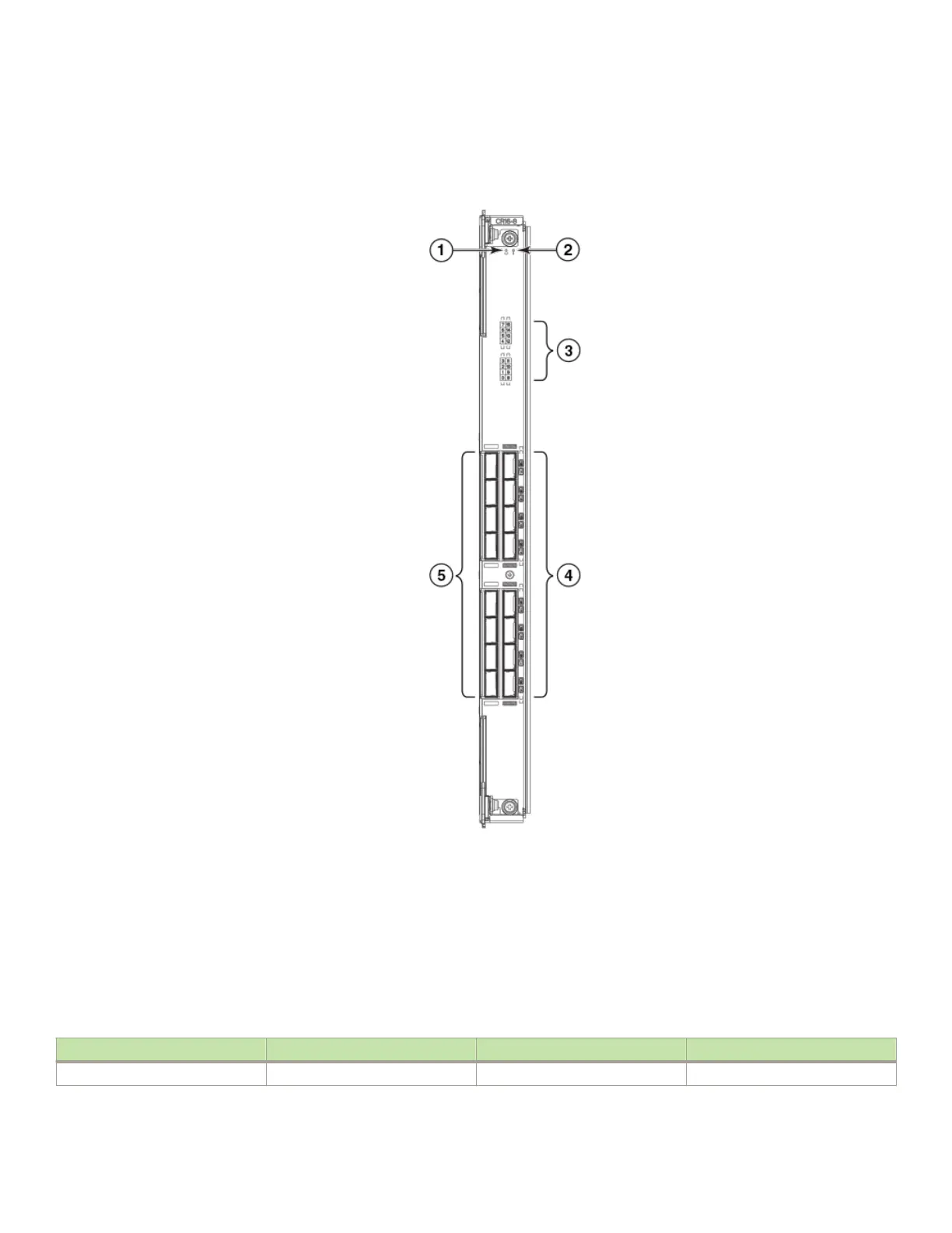
FIGURE 34 Core switch blade (CR16-8)
1. Power LED
2. Status LED
3. QSFP port map and trunking diagram
4. QSFP connectors
5. QSFP connectors
The following table describes the core switch blade LED patterns and the recommended actions for those patterns.
TABLE 12
CR blade LED descriptions
LED purpose Color Status Recommended action
Power Steady green CR16-8 blade is on. No action required.
Determining the status of a core switch blade (CR16-8)
Brocade DCX 8510-8 Backbone Hardware Installation Guide
90 53-1002180-15

 Loading...