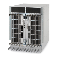
TABLE 12 CR blade LED descriptions (continued)
LED purpose Color Status Recommended action
No light (LED is o) CR16-8 blade is not on. Ensure that the blade is rmly
seated and has power.
Status No light (LED is o) CR16-8 blade is either healthy or
does not have power.
Verify that the power LED is on.
Steady amber CR16-8 blade is faulty or the
switch is still booting.
Ensure that the blade is rmly
seated and the switch has
completed booting. If the LED
remains amber, consult the supplier
for your Brocade device.
Slow-ashing amber (on 2
seconds, then o 2 seconds)
CR16-8 blade is not seated
correctly or is faulty.
Pull the blade out and reseat it. If
the LED continues to ash, replace
the blade.
Fast-ashing amber (on 1/2
second, then o 1/2 second)
Environmental range exceeded. Check for out-of-bounds
environmental condition and correct
it.
QSFP connector status LED No light (LED is o) No QSFP module, all four QSFP
ports are disabled
No action needed if the QSFP is
not installed or verify that the QSFP
is fully inserted.
Steady amber QSFP module is in, all four ports
have no signal/no sync.
Ensure that the cable is properly
connected. If the LED remains
amber, consult the supplier for your
Brocade device.
Blinking amber Port is disabled or faulted, FC link
activity, segmented, loopback
mode, also during transition
between cable plug in and all four
ports online.
Check for console messages or
wait for all four ports to come
online.
Steady green QSFP module is in and all ports are
online.
No action needed.
Refer to the Port Numbering section of this guide for a map of the ports and a table of external ports to internal ports as shown
in the slotShow command.
Determining the status of a power supply
Complete the following steps to determine the status of a power supply. The Brocade DCX 8510-8 can have up to four power supplies.
1. Check the LED indicator on the power supply. The LED patterns may temporarily change during POST and other diagnostic
tests; for information about how to interpret the LED patterns, refer to the following table. Be sure to check all the power supply
modules.
Determining the status of a power supply
Brocade DCX 8510-8 Backbone Hardware Installation Guide
53-1002180-15 91

 Loading...