Brookeld Engineering Labs., Inc. Page 92 Manual No. M13-167-A0415
A.3 Setting the Gap
1. Movethetoggleswitchtotheright;thiswillturn
on(enable)theGapSettingFeature.ThePilot(red)
lightwillbeilluminated.
Note: The motor should be OFF.
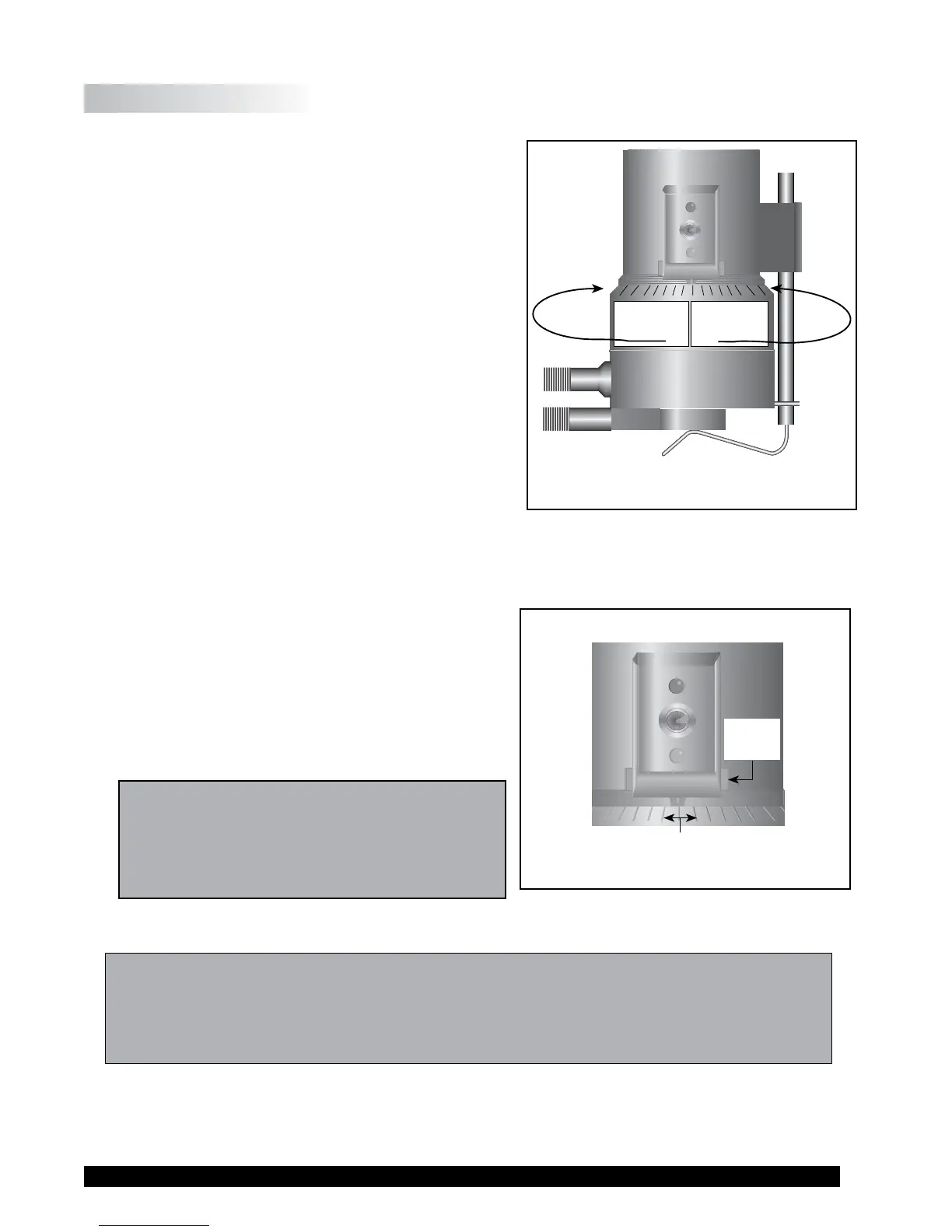
2. Ifthecontactlight(yellow)isilluminated,turnthe
micrometeradjustmentringclockwise(asyoulook
downontheinstrument)untilthelightisnolonger
illuminated(seeFigure A-5).
3. Iftheyellowcontactlightisnotilluminated,slowly
turn the micrometer adjustment ring in small
increments (one or two scale divisions) counter-
clockwise.
Continuemovingthemicrometeradjustment ring
slowly counter-clockwise until the contact light
(yellow) rst turns on. THIS IS THE “HIT
POINT.”
4. Adjusttheslidingreferencemarker,rightorleft,
totheclosestfullscaledivisionmark(see Figure
A-6).
5. Turn the micrometer adjustment ring one scale
divisiontothelefttomeetthelineonthesliding
reference marker. THE YELLOW CONTACT
LIGHT SHOULD GO OFF.
6. You have established the gap space needed for
measurement. Now turn the toggle switch OFF
(left);theredpilotlightshouldgooff.
Theviscosityofelectricallyconductiveuids
maybeaffectedifreadingsaretakenwiththe
ElectronicGapSettingfeature“on”.Besureto
shutthefeature“off”beforetakingreadings!
7. Carefullyremovethesamplecup.
Note:
1. The cup may be removed and replaced without resetting the gap if the micrometer
adjustmentringhasnotbeenmoved.
2. Removethespindlefromtherheometerwhencleaning.
3. Re-establishthehitpointeverytimethespindleisattached/detached.
Moves Away
from Hit Point
(clockwise)
LEFTx
Moves Towards
Hit Point
(counter-clockwise)
RIGHT
Full Scale
Division Marks
Sliding
Reference
Marker
Figure A-5
Figure A-6