3 - 29
Rotary hook drive mechanism
Main unit
Assembly
4
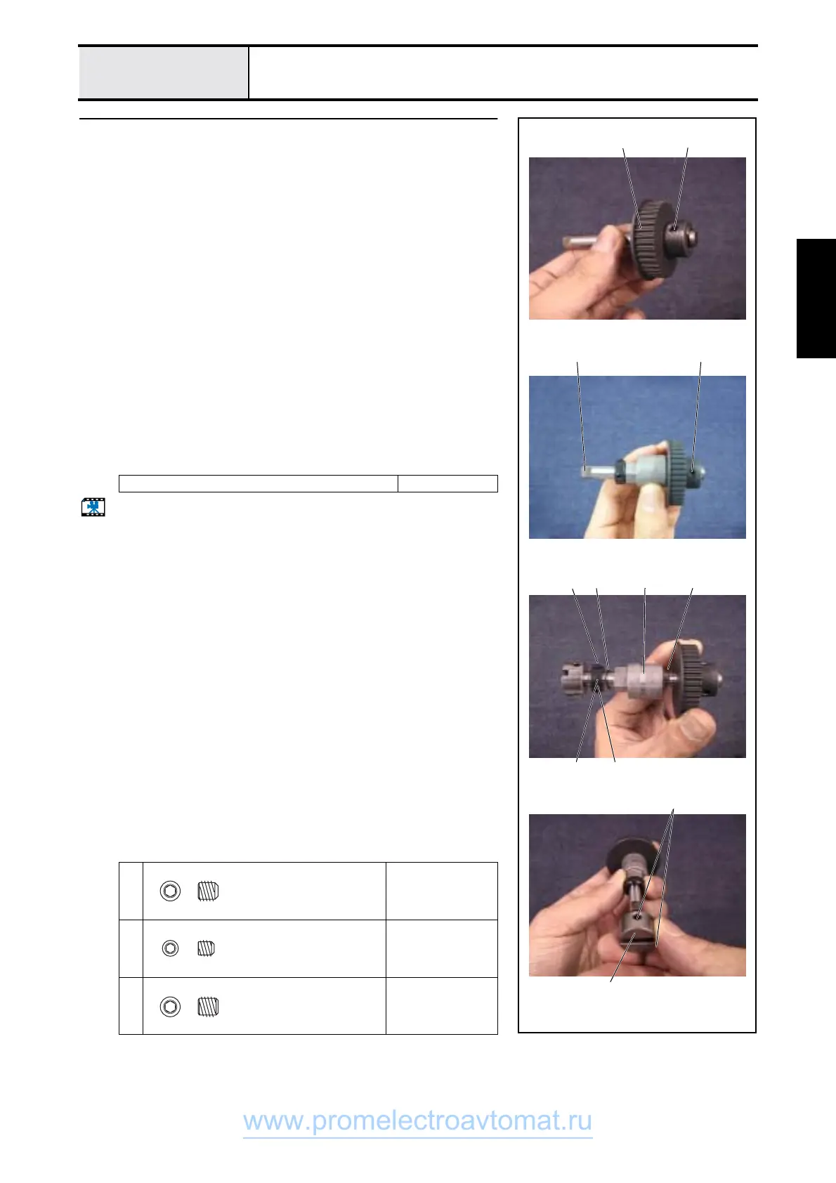
Lower shaft A assy. assembly
1. Attach retaining ring E6 to lower shaft A.
2. Attach timing pulley D 1 to lower shaft A using screws 1 (set screw,
socket (CP) M5X5) (three)
*Key point
• Hand start screw 1, and fully tighten after 4 - 8 "Needle bar
rise adjustment."
• Align one of the three screw holes 3 in timing pulley D with
the D cut 2 in lower shaft A.
3. Attach the thrust washer 4, eccentric shaft bushing 5, thrust washer 4,
set screw collar 6 to lower shaft A, and secure the set screw collar 6 with
screws 2 (set screw, socket (CP) M4X4) (two).
*Key point
• Ground surface of the set screw collar toward the eccentric
shaft bushing.
4. Apply 1 – 2 drops of Sewing Lube to the eccentric shaft bushing 5.
5. Attach the joint 7 to lower shaft A using screws 3 (set screw, socket (FT)
M5X5) (two).
*Key point
• Joint groove parallel to D cut in lower shaft A
Start movie clip (CD-ROM version only)
Sewing Lube 1 – 2 drops
1
Torque
Hand start
2
Torque
0.78 - 1.18 N-m
3
Torque
1.18 - 1.57 N-m
1 1
6
7
2 454
3
2
12
Set Screw, Socket (CP
M5X5
Color; Black
Set Screw, Socket (CP
M4X4
Color; Black
Set Screw, Socket (FT)
M5X5
Color; Black
www.promelectroavtomat.ru
 Loading...