3 - 30
Rotary hook drive mechanism
Main unit
5
Lower shaft A attachment
1. Rotate the upper shaft by hand, and bring the needle bar to its highest point
(timing shutter base line forward).
2. Rotate the feed module lower shaft B, and bring the solid dot 1 on the
outer rotary hook to the front and the D cut on lower shaft B to face straight
up.
3. Apply a small amount of Epnoc Grease AP to lower shaft A and the (feed
module) lower shaft B joint.
4. Place the timing belt (rotary hook drive) on the lower shaft A assy. timing
pulley, and attach the lower shaft A assy. 2 and the disk 3.
*Key point
• The needle bar should be at the highest point.
• The solid circle mark on the outer rotary hook should be
forward.
• The lower shaft B socket set screw (feed module) should be
straight up.
• The lower shaft A side joint socket set screw should face
forward.
5. Attach the lower shaft bushing presser (4) to the arm bed and hand start
screws 1 (two).
*Key point
• Fully tighten after 4 - 7 "Timing belt tension adjustment."
6. Apply 1 – 2 drops of Sewing Lube to the lower shaft assy. eccentric shaft
bushing shaft hole.
Start movie clip (CD-ROM version only)
Epnoc Grease AP Small amount
Sewing Lube 1 – 2 drops
1
Torque
1.18 - 1.57 N-m
1
Base line
4
23
D cut
1
Upper shaft
Giza Tite
5X16
Color; Gold
6
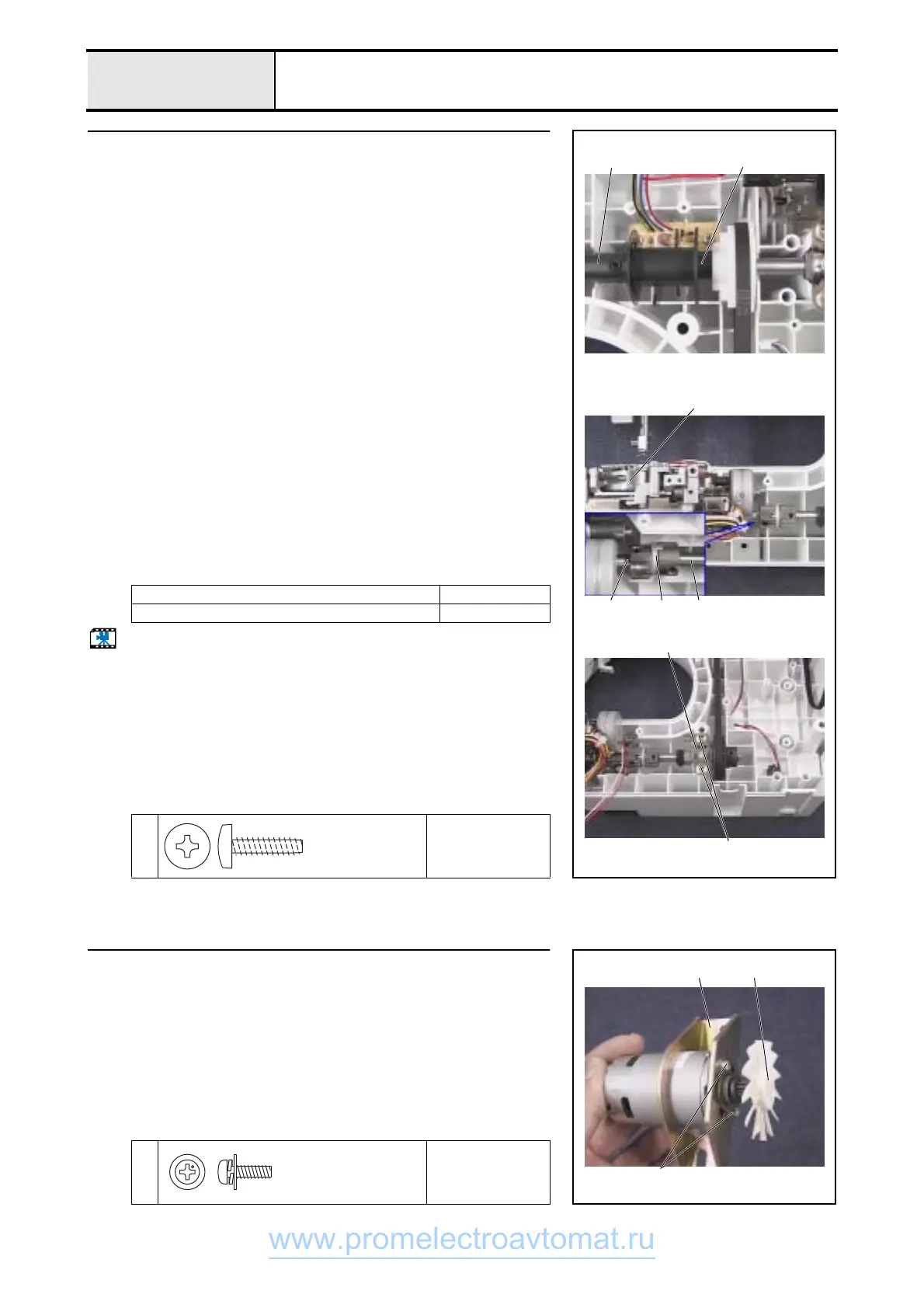
Main motor assy. assembly
1. Attach the main motor to the motor holder 1 using screws 1 (two).
2. 2Attach the motor fan to the main motor.
1
Torque
0.78 - 1.18 N-m
2
1
1
Screw, Pan (S/P washer)
M3X10DB
Color; Silver
www.promelectroavtomat.ru
 Loading...