3 - 61
Needle-presser module
Modules
Assembly
22
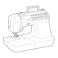
Needle bar assembly attachment
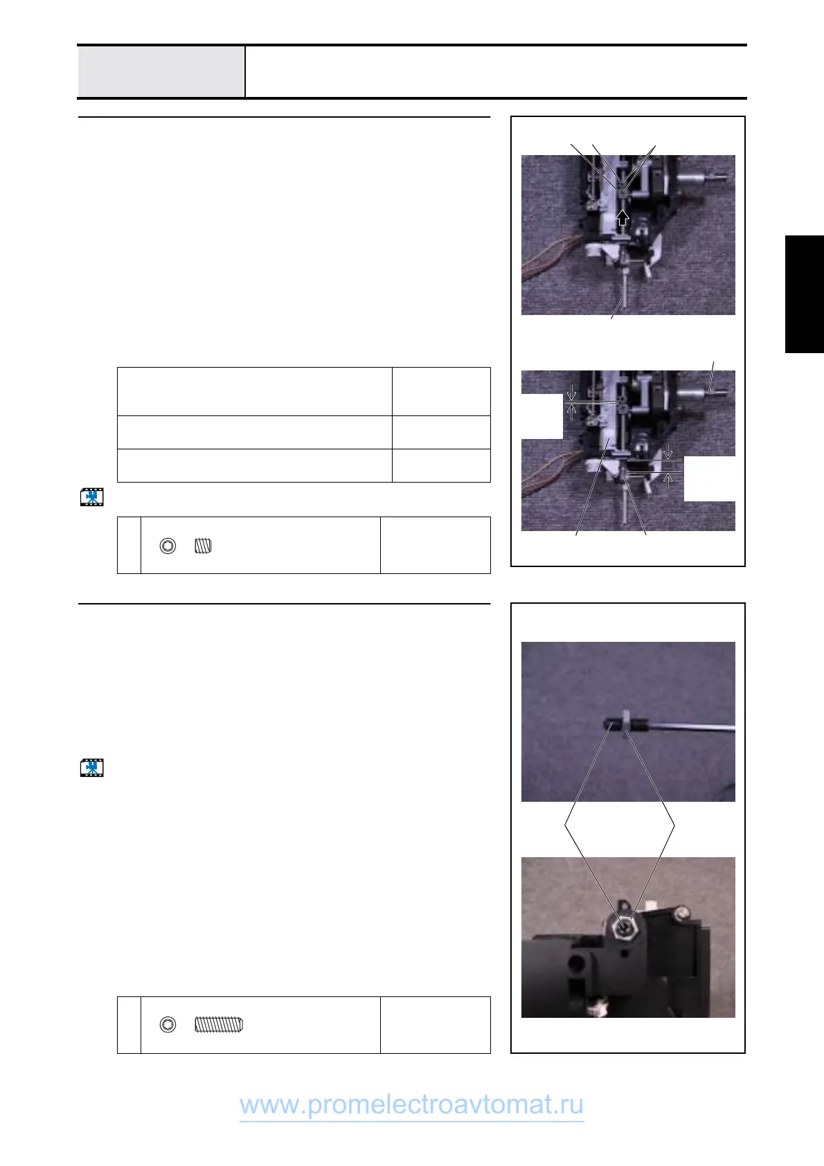
1. Apply a small amount of Epnoc Grease AP to the needle thread block 1.
2. Attach the needle bar 2 to the needle bar crank rod assy. needle bar block
3 and the needle thread block 1, and hand start screws 1 (two).
(Fully tighten after 4 - 9 "Needle bar height adjustment," and 4 - 23"Adjust
the needle thread block.")
*Key point
• With the unit shaft D cut
4
facing forward, the upper surface of the
needle block
5
and the base of the needle bar supporter assy.
6
should be adjusted to an approximately 10 mm separation.
• Adjust the space between the needle thread block 1 and the
needle bar block 3 to approximately 2 mm.
• When the needle thread block 1 is viewed from the front, it is
secured in a position turned slightly counterclockwise (see 4 -
23 "Adjust the needle thread block").
Start movie clip (CD-ROM version only)
Lubricate the needle bar block needle bar crank
joint area on the needle bar block with Molykote
(Sewing Lube 90% + Molykote dispersion)
1 – 2 drops
Apply Epnoc Grease AP to the pin sliding part of
the needle thread block.
Small amount
Lubricate the needle bar supporter assy. needle
operating area with Sewing Lube.
1 – 2 drops
1
Torque
Hand start
3 1
Approxima
tely 2 mm
between 1
and 3
4
6
Approximate
ly 10 mm
between 5
and 6
2
5
1
Set Screw, Socket (FT)
M4X4
Color; Black
23
Lock nut attachment
1. Install screw 1 in the locknut 1.
*Key point
• Screw the screw 1 in approximately half its length.
2. Install 1 in the upper unit holder.
*Key point
• Tighten until the lock nut 1 hits the upper unit holder.
3. Tighten the lock nut 1.
Start movie clip (CD-ROM version only)
1
Torque
0.39 - 0.49 N
−
m
1
1
Set Screw, Socket (CP
M4X12
Color; Black
www.promelectroavtomat.ru
 Loading...