2 - 5
Main parts
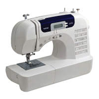
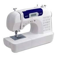
Main unit
Disassembly
6
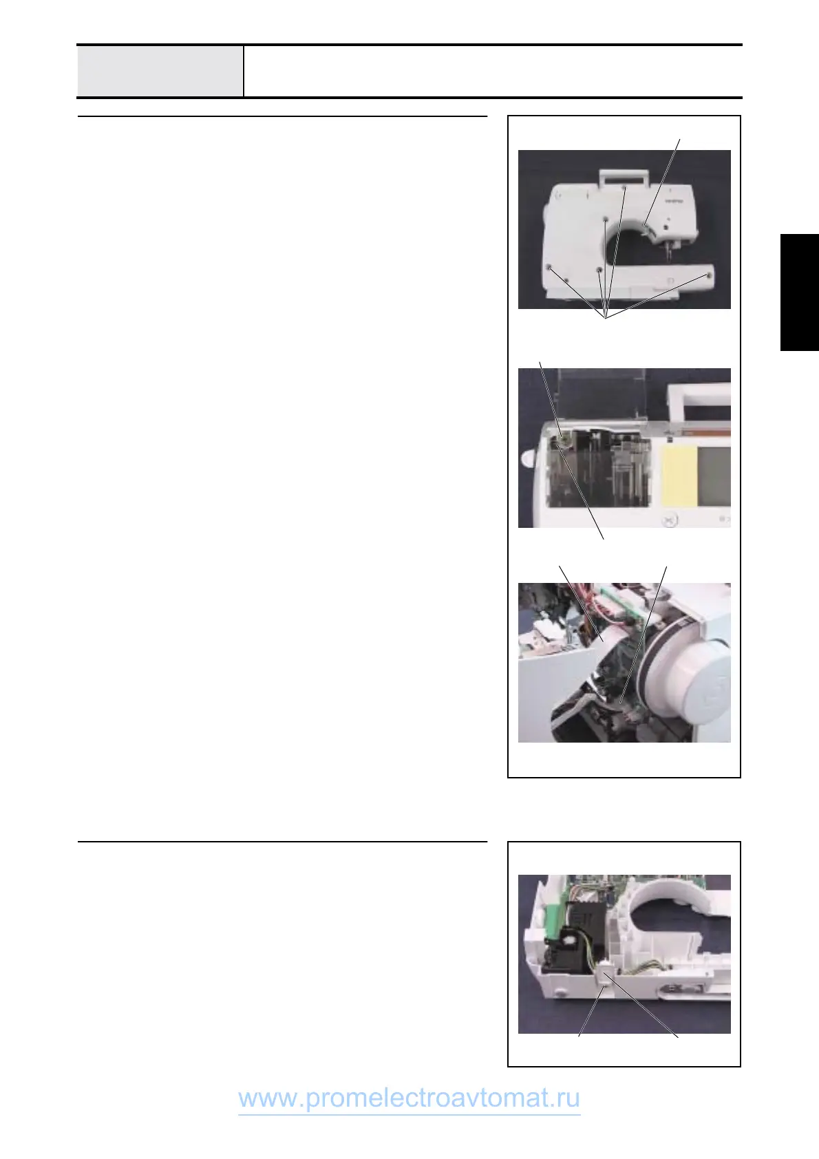
Front cover assy. removal
1. Remove screws 1 (one on the front side, five on the rear side) and screw
2 (one on rear side).
2. Remove the front cover from the arm bed.
*Key point
• Be careful to push the thread tension mechanism spring 1 to
the left side, and not damage it when removing the front cover.
• When the front cover is removed, disconnect the operation S2
(or S3) PCB assy. flat cable 2 and the power PCB assy. lead
wire connector 3 from the main PCB assy. on the arm bed
side.
1
3
1
(rear)
2
1
(front)
2
7
Base removal
1. Remove the screw 1, and detach the base 1 from the front cover.
11
www.promelectroavtomat.ru
 Loading...